CB1

Product Profile
The BIGTREETECH CB1 is launched to provide a great solution to the insane shortage of Raspberry Pi CM4. It outputs signals to the motherboard via the fast and convenient two 100 pins micro BTB connection header. Moreover, it is onboard 2.4G WiFi.
Product Link: BIGTREETECH Official Website
Features Highlights
| Component | Specifications |
|---|---|
| CPU | ALLWINNER H616, Quad-core Cortex-A53 @1.5GHz |
| GPU | Mali G31 MP2, Support OpenGL3.2 |
| RAM | 512MB/1GB DDR3L SDRAM |
| Display | Compatible with HDMI2.0A Interface, Support 4K Displays |
| USB | Compatible with USB2.0 Interface |
| Network | Support 100M Ethernet + 100M WiFi |
| BTB connector | Having the same BTB header as the Raspberry Pi CM4 |
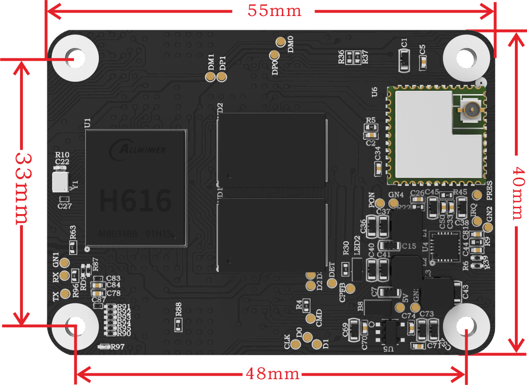
Specifications
| Product Size | 40mm x 55mm |
|---|---|
| Mounting Size | 33mm x 48mm |
| Input Voltage | 5V±5%/2A |
| Output Voltage | 3.3V±2%/100mA |
| Output Voltage | 1.8V±2%/100mA |
| WiFi | 2.4G/802.11 b/g/n |
Dimensions
Schematic
BIGTREETECH_CB1_V22_220812_SCH
Pinout
40 pin GPIO
The 40 pin GPIO on the motherboard when CB1 is used with motherboard like Manta M4P, M5P, M8P, PI4B_Adapter, etc.
| Pin | Signal | Description | Pin | Signal | Description |
|---|---|---|---|---|---|
| 1 | 3.3V | 2 | 5V | ||
| 3 | NC | 4 | 5V | ||
| 5 | NC | 6 | GND | ||
| 7 | PC7 | GPIO71 | 8 | PH0 | GPIO224, UART0_TX |
| 9 | GND | 10 | PH1 | GPIO225, UART0_RX | |
| 11 | PC14 | GPIO78 | 12 | PC13 | GPIO77 |
| 13 | PC12 | GPIO76 | 14 | GND | |
| 15 | PC10 | GPIO74 | 16 | PC11 | GPIO75 |
| 17 | 3.3V | 18 | PC9 | GPIO73 | |
| 19 | PH7 | GPIO231, SPI1_MOSI | 20 | GND | |
| 21 | PH8 | GPIO232, SPI1_MISO | 22 | NC | |
| 23 | PH6 | GPIO230, SPI1_CLK | 24 | NC | |
| 25 | GND | 26 | PG8 | GPIO200 | |
| 27 | NC | 28 | PG7 | GPIO199 | |
| 29 | NC | 30 | GND | ||
| 31 | PG6 | GPIO198 | 32 | PG9 | GPIO201 |
| 33 | NC | 34 | GND | ||
| 35 | PC6 | GPIO70 | 36 | NC | |
| 37 | PC15 | GPIO79 | 38 | PH10 | GPIO234, IR_RX |
| 39 | GND | 40 | PC8 | GPIO72 |
2 * 100 pins
| A Pin | Signal | Description | A Pin | Signal | Description |
|---|---|---|---|---|---|
| 1 | GND | 2 | GND | ||
| 3 | NC | 4 | EPHY-TXP | Ethernet TX Positive | |
| 5 | NC | 6 | EPHY-TXN | Ethernet TX Negative | |
| 7 | GND | 8 | GND | ||
| 9 | NC | 10 | EPHY-RXP | Ethernet RX Positive | |
| 11 | NC | 12 | EPHY-RXN | Ethernet RX Negative | |
| 13 | GND | 14 | GND | ||
| 15 | LINK_LED | Ethernet LED | 16 | NC | |
| 17 | SPD_LED | Ethernet LED | 18 | NC | |
| 19 | NC | 20 | NC | ||
| 21 | PH5 | System LED(ACT) | 22 | GND | |
| 23 | GND | 24 | PC15 | ||
| 25 | PC8 | 26 | PC6 | ||
| 27 | PH10 | 28 | NC | ||
| 29 | NC | 30 | PG6 | ||
| 31 | PG9 | 32 | GND | ||
| 33 | GND | 34 | NC | ||
| 35 | PG7 | 36 | NC | ||
| 37 | PG8 | 38 | PH6 | ||
| 39 | NC | 40 | PH8 | ||
| 41 | NC | 42 | GND | ||
| 43 | GND | 44 | PH7 | ||
| 45 | PC9 | 46 | PC10 | ||
| 47 | PC11 | 48 | PC12 | ||
| 49 | PC13 | 50 | PC14 | ||
| 51 | SoC_RX | DEBUG UART | 52 | GND | |
| 53 | GND | 54 | PC7 | ||
| 55 | SoC_TX | DEBUG UART | 56 | NC | |
| 57 | SDC0-CLK | MicroSD Card | 58 | NC | |
| 59 | GND | 60 | GND | ||
| 61 | SDC0-D3 | MicroSD Card | 62 | SDC0-CMD | MicroSD Card |
| 63 | SDC0-D0 | MicroSD Card | 64 | PG11 | |
| 65 | GND | 66 | GND | ||
| 67 | SDC0-D1 | MicroSD Card | 68 | PG12 | |
| 69 | SDC0-D2 | MicroSD Card | 70 | PG13 | |
| 71 | GND | 72 | PG14 | ||
| 73 | PG16 | 74 | GND | ||
| 75 | NC | 76 | PI16 | MicroSD Card detect | |
| 77 | 5V | 78 | NC | ||
| 79 | 5V | In 2A | 80 | NC | |
| 81 | 5V | In 2A | 82 | NC | |
| 83 | 5V | In 2A | 84 | 3.3V | Out 200mA |
| 85 | 5V | In 2A | 86 | 3.3V | Out 200mA |
| 87 | 5V | In 2A | 88 | 1.8V | Out 100mA |
| 89 | NC | 90 | 1.8V | Out 100mA | |
| 91 | NC | 92 | PWRON | ||
| 93 | FEL | 94 | NC | ||
| 95 | NC | 96 | NC | ||
| 97 | NC | 98 | GND | ||
| 99 | Recovery | 100 | Reset |
| B Pin | Signal | Description | B Pin | Signal | Description |
|---|---|---|---|---|---|
| 101 | NC | 102 | NC | ||
| 103 | USB1-DM | Host USB1 | 104 | LineOut L | |
| 105 | USB1-DP | Host USB1 | 106 | LineOut R | |
| 107 | GND | 108 | GND | ||
| 109 | NC | 110 | NC | ||
| 111 | TV_OUT | CVBS OUT | 112 | NC | |
| 113 | GND | 114 | GND | ||
| 115 | NC | 116 | NC | ||
| 117 | NC | 118 | NC | ||
| 119 | GND | 120 | GND | ||
| 121 | NC | 122 | NC | ||
| 123 | NC | 124 | NC | ||
| 125 | GND | 126 | GND | ||
| 127 | NC | 128 | USB3-DM | Host USB3 | |
| 129 | NC | 130 | USB3-DP | Host USB3 | |
| 131 | GND | 132 | GND | ||
| 133 | NC | 134 | USB2-DM | Host USB2 | |
| 135 | NC | 136 | USB2-DP | Host USB3 | |
| 137 | GND | 138 | GND | ||
| 139 | NC | 140 | USB0-DM | OTG USB | |
| 141 | NC | 142 | USB0-DP | OTG USB | |
| 143 | NC | 144 | GND | ||
| 145 | NC | 146 | NC | ||
| 147 | NC | 148 | NC | ||
| 149 | NC | 150 | GND | ||
| 151 | HCEC | HDMI CEC | 152 | NC | |
| 153 | HHPD | HDMI HotPlug | 154 | NC | |
| 155 | GND | 156 | GND | ||
| 157 | NC | 158 | NC | ||
| 159 | NC | 160 | NC | ||
| 161 | GND | 162 | GND | ||
| 163 | NC | 164 | NC | ||
| 165 | NC | 166 | NC | ||
| 167 | GND | 168 | GND | ||
| 169 | NC | 170 | HTX2P | HDMI TX2 Positive | |
| 171 | NC | 172 | HTX2N | HDMI TX2 Negative | |
| 173 | GND | 174 | GND | ||
| 175 | NC | 176 | HTX1P | HDMI TX1 Positive | |
| 177 | NC | 178 | HTX1N | HDMI TX1 Negative | |
| 179 | GND | 180 | GND | ||
| 181 | NC | 182 | HTX0P | HDMI TX0 Positive | |
| 183 | NC | 184 | HTX0N | HDMI TX0 Negative | |
| 185 | GND | 186 | GND | ||
| 187 | NC | 188 | HTXCP | HDMI CLK Positive | |
| 189 | NC | 190 | HTXCN | HDMI CLK Negative | |
| 191 | GND | 192 | GND | ||
| 193 | NC | 194 | NC | ||
| 195 | NC | 196 | NC | ||
| 197 | GND | 198 | GND | ||
| 199 | HSDA | HDMI I2C | 200 | HSCL | HDMI I2C |
Software Configuration
Network Settings
Ethernet
Plug-and-play with an Ethernet cable, no additional setup required.
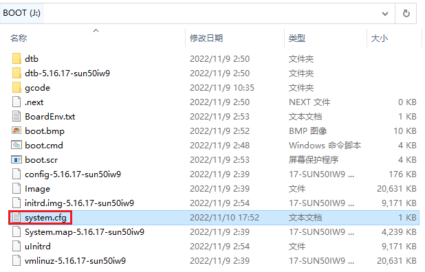
WiFi Settings
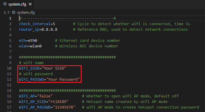
After the OS writes to the SD card, there is a FAT32 partition named BOOT, open system.cfg file with Notpad, Notpad++ or VSCode.
Tip
Set WIFI_SSID as your actual wifi name and WIFI_PASSWD as your actual wifi password, The space character can be parsed normally without additional escape character.
For example:
After the OS writes to the SD card, there is a FAT32 partition named BOOT, open BoardEnv.txt file with Notpad, Notpad++ or VSCode.
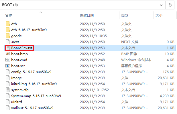
Set as required as shown in the figure below.
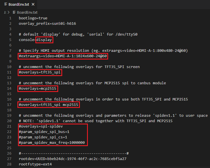
The default value is console=display, This means that the UART0 of CB1 is used as the debugging port by default. We can use MobaXterm to connect to CB1 by UART0 and debug. If klipper wants to use UART0 to control the motherboard, we need to set it to console=serial, now klippe can use UART0 as /dev/ttyS0.
CB1 will automatically identify the HDMI resolution, but if your HDMI screen cannot report the resolution through the EDID normally, we can forcibly specify the resolution of CB1 output by uncomment extraargs=video and set the actual resolution.
For example:
# BTT-HDMI7 resolution = 1024x600
extraargs=video=HDMI-A-1:1024x600-24@60
# BTT-HDMI5 resolution = 800x480
extraargs=video=HDMI-A-1:800x480-24@60
Uncomment overlays=tft35_spi to enable TFT35 SPI screen.
Uncomment overlays=mcp2515 to enable MCP2515 spi to canbus module.
Uncomment overlays=tft35_spi mcp2515 If you want to use both TFT35 SPI screen and MCP2515 spi to canbus module
uncomment the following overlays and parameters to release spidev1.1 to user space, And spidev1.1 cannot be used together with TFT35_SPI and MCP2515.
Note
TFT35 SPI and MCP2515 multiplex a group of SPI1
SSH Connection
SSH Application
Install the ssh application Mobaxterm: https://mobaxterm.mobatek.net/download-home-edition.html
Insert the Micro SD card (installed OS) to motherboard, wait for system to load after power on, aprox. 1-2min. the ACT LED on the motherboard will flash continuously after startup successfully.
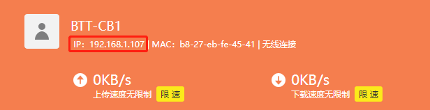
The device will automatically be assigned a IP address after successfully connected to the network
Find the device IP address in your router page
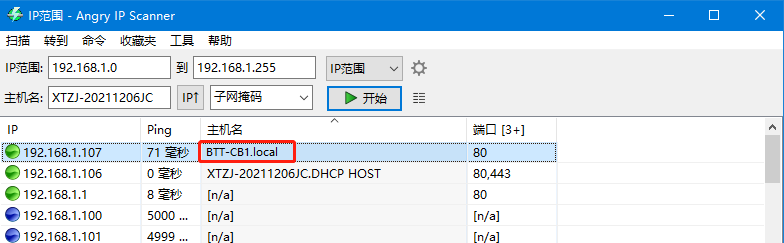
Or use the https://angryip.org/ tool, scan all IP address in the current network organize by names, find the IP named Hurakan, BTT-CB1 like shown below
Open Mobaxtermand click “Session”, and click “SSH”, inset the device IP into Remote host and click “OK” (note: your computer and the device needs to be in the same network)

Input the login name and password to enter the SSH terminal interface.
password dose not show up in terminal when type
Software Installation
-
Download the OS Image
Please download and install the OS image we provided: https://github.com/bigtreetech/CB1/releases
-
Download and Install Writing Software
The official Raspberry Pi Imager: https://www.raspberrypi.com/software/
balenaEtcher: https://www.balena.io/etcher/
Both of the above software can be used, just choose one to download and install
-
Format SD card
Warning
Formatting the SD card will remove all data in SD card. Ensure backup data before formatting.
Normally, you can format the SD card with the tools provided by the computer system. Completely format the SD card with professional SD card format software. https://www.sdcard.org/downloads/formatter/
-
Write OS
Insert a MicroSD card to your computer through a card reader.
Select the image that you downloaded.
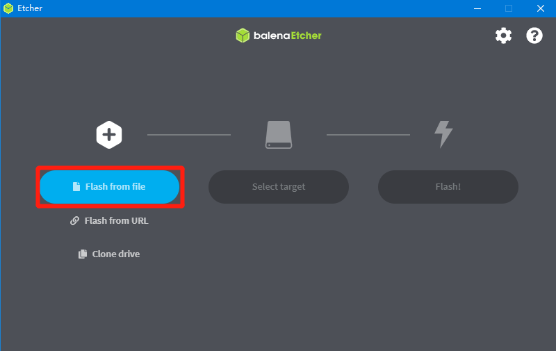
Select the MicroSD card and click
FlashWarning
Flashthe image will format the MicroSD card. Be careful not to select the wrong storage device, otherwise the data will be formatted.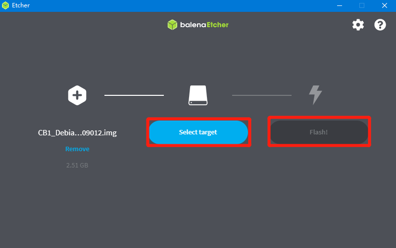
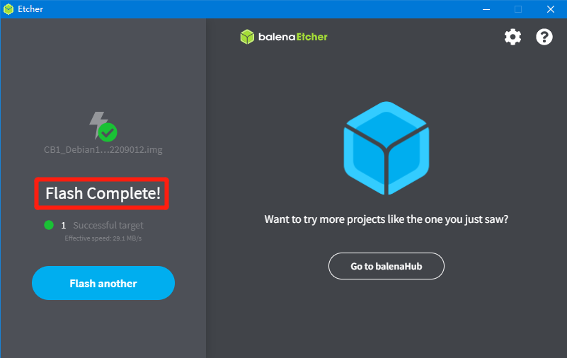
Wait for the writing to finish.
Product Purchase Link
Purchase Link:
https://biqu.equipment/products/pi4b-adapter-v1-0?variant=40353646051426
If you have any issues with the product, please submit a support ticket.
https://biqu3d.com/pages/submit-a-ticket
Navigation:
BIQU Official Website: http://biqu3d.com
BIGTREETECH Official Website: http://bigtree-tech.com
Online Store: https://biqu.equipment
BIGTREETECH Official Group: https://www.facebook.com/groups/bigtreetech
Discord: https://discord.gg/hhZsV7zk
Reddit: https://www.reddit.com/r/BIGTREETECH/