TMC5160T Plus
Product Profile
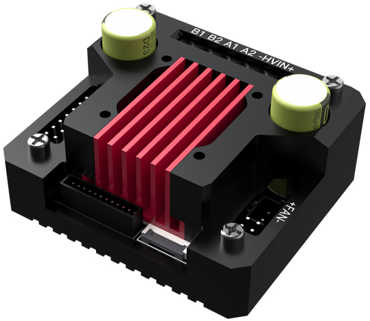
TMC5160T Plus is a high-power stepper motor driver control module, featuring 8 high-power MOSFETs separately mounted on the board with a maximum voltage of 60V. This supports a wider range of stepper motors and offers greater adaptability.
Product Link: BIGTREETECH Official Website
Features Highlights
-
8 high-power MOSFETs separately mounted on the board with 100V voltage resistance, 93A current resistance, and equivalent resistance as low as 6mΩ, significantly enhancing the drive's performance.
-
Supports a maximum voltage of 60V, a maximum effective current (IRMS) of 10.6A, and a sine wave peak current of up to 15A.
-
StealthChop™ mode and SpreadCycle™ mode selectable, with standalone mode, UART mode, and SPI mode selectable.
-
Generates significantly less heat compared to other drives with the same chip model, and outperforms others on the market.
-
Can prevent motor jitter and avoid losing steps.
-
Tested to drive 36, 42, 57, 86, etc., stepper motors.
-
ESD protection on the drive power, logic power, etc., to prevent damage due to power fluctuations and static electricity.
-
On-board 24V always-on fan interface facilitates active cooling.
-
Encoder interface reserved for DIY usage.
-
Integrated heat sink design, providing high heat dissipation while enhancing structural integrity and aesthetics.
-
Supplied with adapters and wires for both standard drives and EZ drive, for user convenience.
-
Heat sink pre-designed with fan mounting holes for DIY fan installation.
Specifications
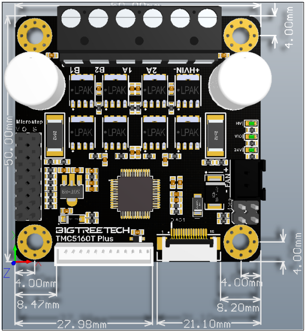
| Dimensions | TMC5160T Plus: 64 x 56 x 32.55mm |
|---|---|
| Dimensions | TMC5160T Plus(W/o case): 58 x 50 x 28mm |
| Drive Chip | TMC5160-TA |
| Input Voltage (HVIN) | 8V - 56V |
| Maximum Effective Current | 10.6A, Sine Wave Peak Current 15A |
| Capacitor | 2 x 560uF |
| Operating Mode | SPI, SD |
| Sampling Resistor | 22mΩ |
Interface Diagram
Pinout/Function
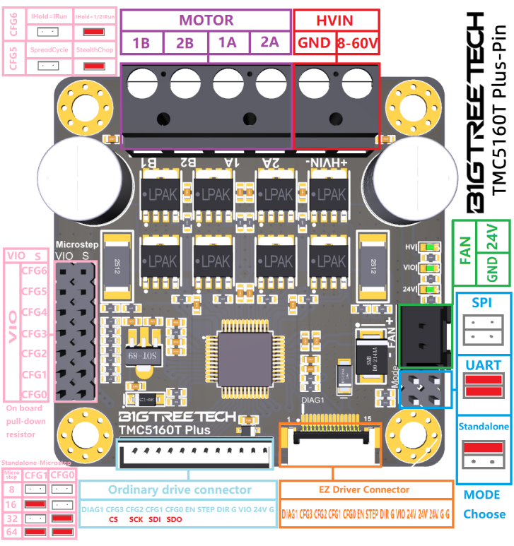
Interface Introduction
Installation and Interface
Connection methods for common motherboards (e.g., SKR3), use the supplied TMC Driver Adaptor and cables to connect the TMC5160T Plus with SKR3 as shown in the diagram:
Warning
TMC Driver Adaptor only support 24v!

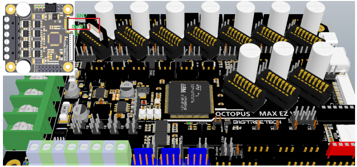
For EZ series motherboards (e.g., Octopus MAX EZ), use the supplied EZ Driver Adaptor and cables to connect the TMC5160T Plus with Octopus MAX EZ as shown in the diagram:
Warning
EZ Driver Adaptor only support 24v!
Software Configuration
Marlin Firmware Settings
Marlin firmware version
Currently, only Marlin 2.0 and later firmware versions support TMC5160's SPI mode.
-
In the Marlin 2.0 firmware, locate and open the "Configuration.h" file, then find the line
#define MOTHERBOARD XXXXXX.XXXXXXrepresents the model of the board being used. Confirm the motherboard you are using.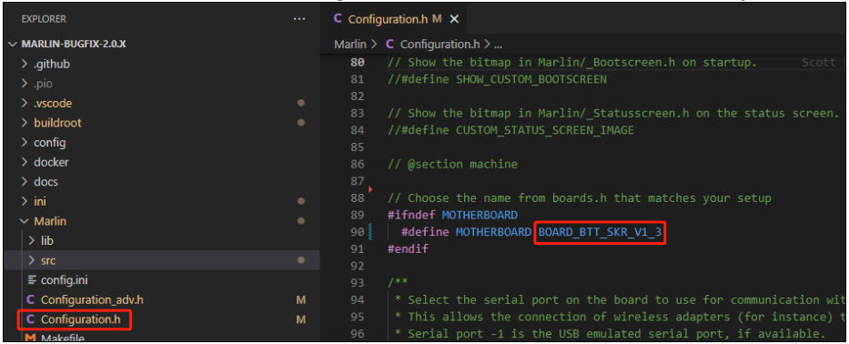
-
In the
Marlin/src/pinsdirectory, find thepins_xxxxxx.hfile corresponding to your board (xxxxxx represents the board model), and then locateX_CS_PIN,Y_CS_PIN,Z_CS_PIN, andEO_CS_PINwithin the file. Modify the pin names following these variables to the pins you are using.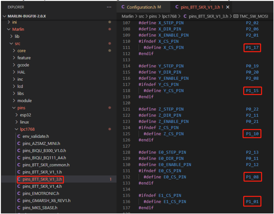
-
In the file from Step 2, locate
#define TMC_SW_MOSI XXX,#define TMC_SW_MISO XXX, and#define TMC_SW_SCK XXX. ChangeXXXto the pins you want to use.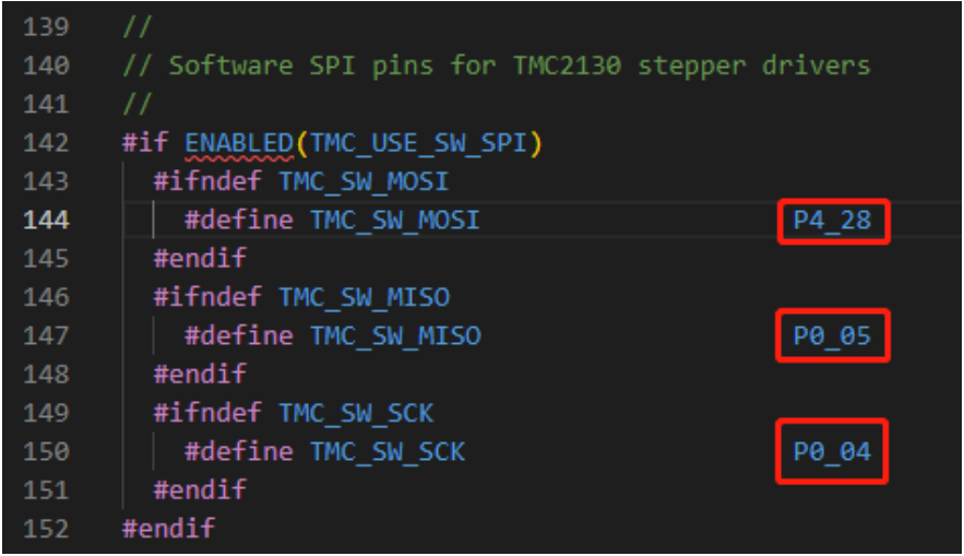
-
Find and open
Configuration_adv.h, then locate#define TMC_USE_SW_SPIand remove the comment symbols//.
-
In the
Configuration_adv.hfile, find#define X_CURRENT,#define X_MICROSTEPS, and#define X_RSENSEand modify the parameters that follow (for each axis being used). TheRSENSEvalue for each used axis should be changed to0.022.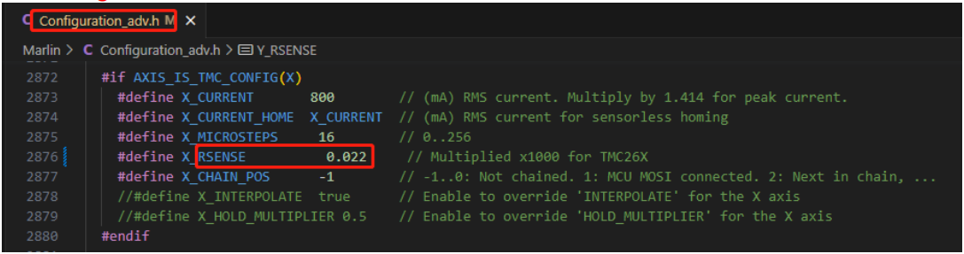
-
Set the corresponding axis drive type to
TMC5160in theConfiguration.hfile.
Klipper Firmware Settings
[tmc5160 stepper_x]
cs_pin: PD2
spi_software_sclk_pin: PC6
spi_software_mosi_pin: PC8
spi_software_miso_pin: PC7
run_current: 1.20
sense_resistor: 0.022
interpolate: False
stealthchop_threshold: 0
# diag1_pin: ^!PF3
# driver_SGT: 2
Check Sense Resistor
The default sense_resistor in Klipper is 0.075. It needs to be set to 0.022.
Precautions
Precautions
Turn off the power before installing the driver to prevent damage.
Do not plug or unplug the driver module with power on to avoid damage.
Be cautious of polarity when connecting; reversing can cause the driver to burn out.
The factory-installed heat sink should not be removed, as doing so will decrease heat dissipation in the absence of thermal interface material.
For large currents (greater than 3A), active cooling is required for normal operation.
This product uses a 0.022R sampling resistor, so the maximum effective driving current is 10.6A.
Pay attention to the power sequence; ensure the driver power is turned on before the logic power. That is, turn on the driver power first, then power on the motherboard.
Regardless of whether the driver uses high or low voltage power delivery, the output voltage from the main control board to the drive must not exceed 24V; exceeding this will damage the driver.