PAD7
Product Profile
The BIGTREETECH Pad 7, a product of Shenzhen BIQU Innovation Technology Co., Ltd., is a tablet equipped with pre-installed Klipper and KlipperScreen. The BTB headers have been engineered to provide users with the flexibility to select from various solutions, including CM4, CB1, and more.
Product Link: https://biqu.equipment/products/bigtreetech-pad-7
Features Highlights
-
The 7-inch IPS touch screen offers a wider field of view, high level of detail, and a comfortable user experience
-
Features a built-in speaker, which allows you to adjust the volume with the volume buttons
-
Having a 3.5mm headphone jack, which enables you to connect headphones or external speakers
-
The touch experience is enhanced with vibration feedback
-
The built-in light sensor adjusts the backlight brightness automatically based on the available light
-
Incorporates the GT911 high-performance touch chip, which supports 5-point touch
-
The bracket attaches securely to the back of the Pad 7 during storage and folding, thanks to the built-in magnets
Specifications
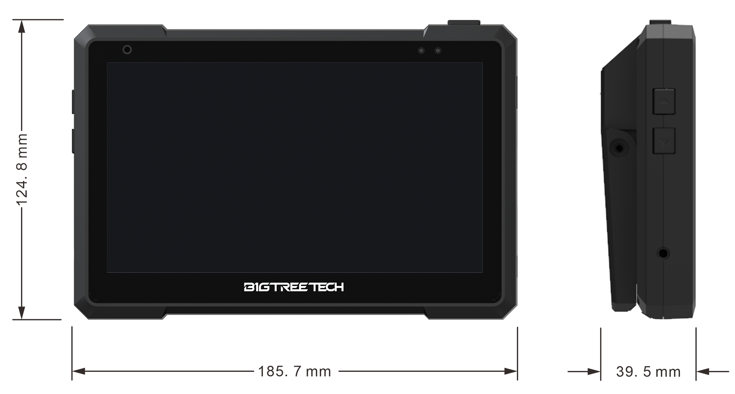
| Dimensions | 185.7 x 124.78 x 39.5 mm |
|---|---|
| Display Viewing Area | 154.2 x 85.92 mm |
| Display | 7 inches, 1024 x 600 resolution, 60Hz refresh rate |
| Viewing Angle | 178° |
| Brightness | 500 Cd/m² |
| Input | DC 12V, 2A |
| Rated Power | 7.3W |
| Display Port | HDMI |
| Touch Port | USB-HID |
| PC Connection | Type-C (CM4 eMMC OS writing) |
| Interface | USB 2.0 x 3, Ethernet, CAN, SPI, SOC-Card |
| Core Board | BIGTREETECH CB1 v2.2, 1GB, accompanied by a SanDisk 32 GB memory card |
Dimensions
Connectivity
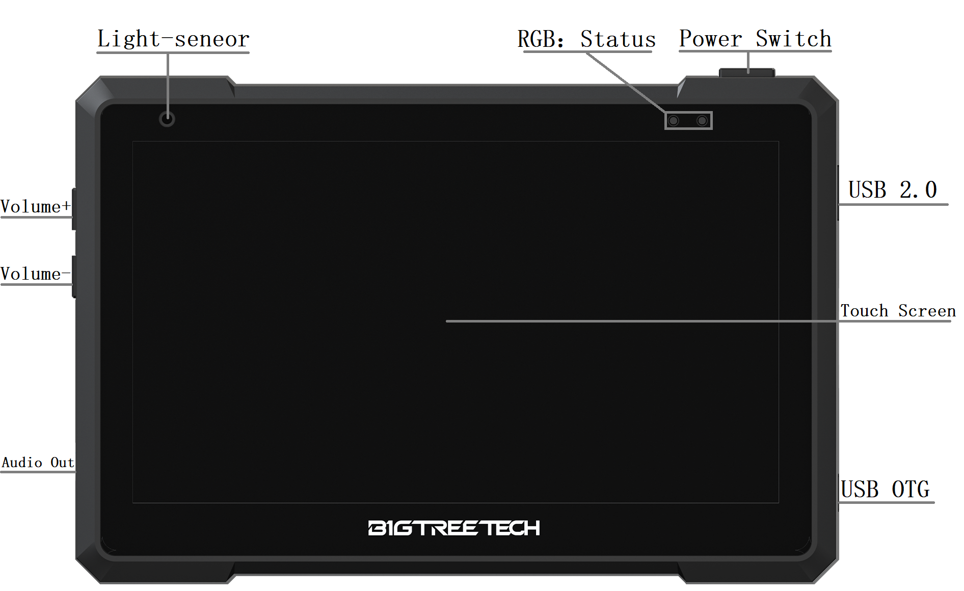
- Light-Sensor: built-in light sensor to automatically adjust the brightness of the backlight based on the intensity of ambient light.
- RGB: Status light.
- USB2.0: USB-Host peripheral interface.
- USB OTG: Communication interface with the host computer.
- Volume-:built-in speaker volume decrease.
- Volume+:Built-in speaker volume increase.
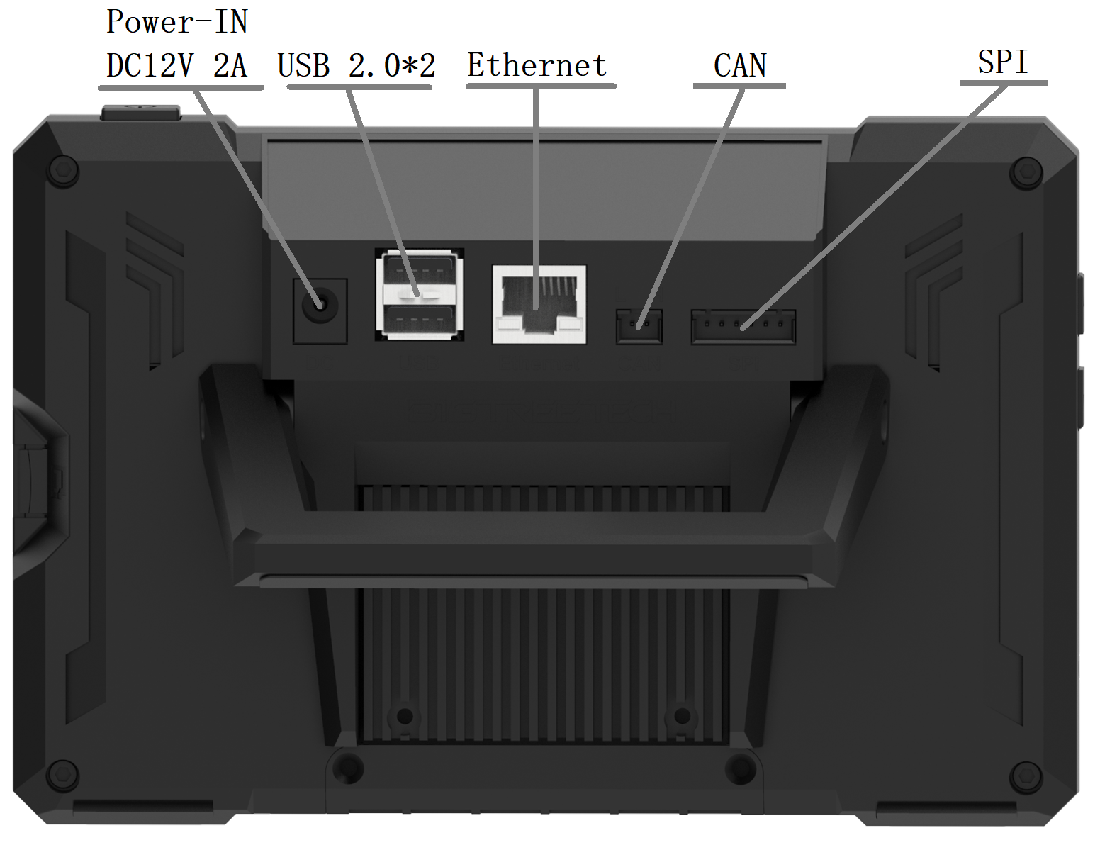
- Power-IN DC12V 2A: coming with a 12V 2A power adapter.
- USB2.0*2: USB host peripheral interface.
- Ethernet: RJ45 (CB1 supports 100M networking, CM4 supports Gigabit networking).
- CAN: CAN peripheral interface (MCP2515 SPI-CAN).
- SPI: SPI peripheral interface (can connect to ADXL345 accelerometer module).
Note: It is not possible to use the CAN interface and the ADXL345 accelerometer SPI interface simultaneously due to the MCP2515 SPI to CAN conversion.
Hardware assembly
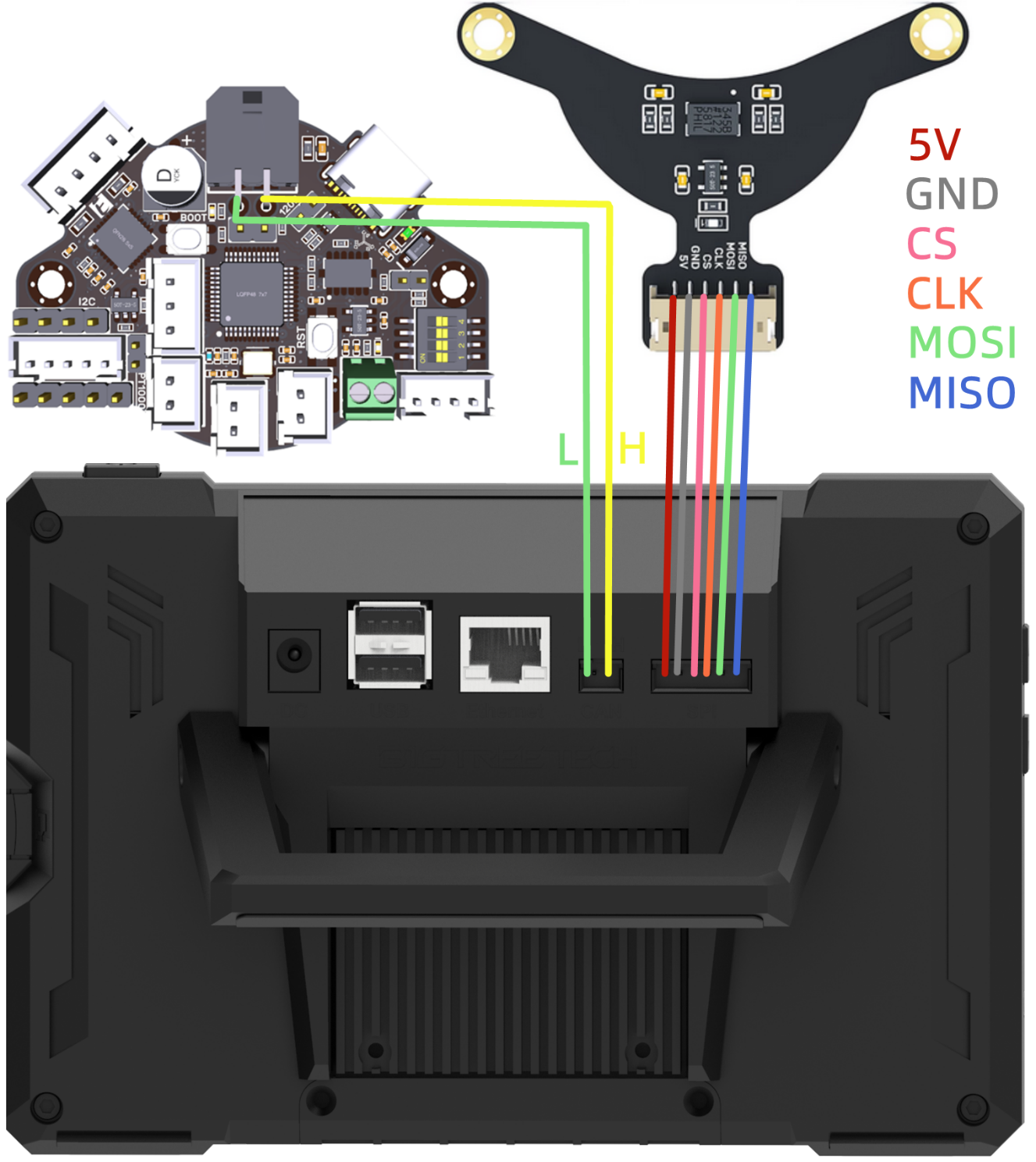
Connection between Pad7, EBB36, and ADXL345
To Replace CB1 with CM4
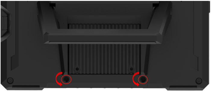
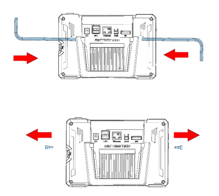
1.Disconnect the power supply, and place the Pad 7 backside up on a flat surface.
2.Use a 1.5 mm hex key to remove the two M2.5 x 3 flat head countersunk screws in a counterclockwise direction.
Slide the bottom cover upwards using your fingers.
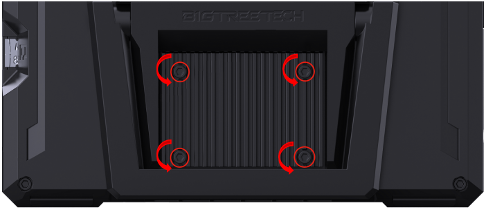
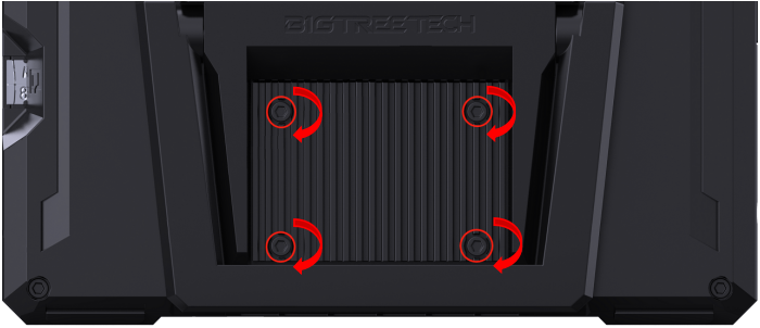
3.Use a 2.0 mm hex key to remove the four M2.5 x 10 socket head cap screws in a counterclockwise direction.
Remove the heatsink.
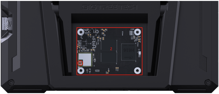
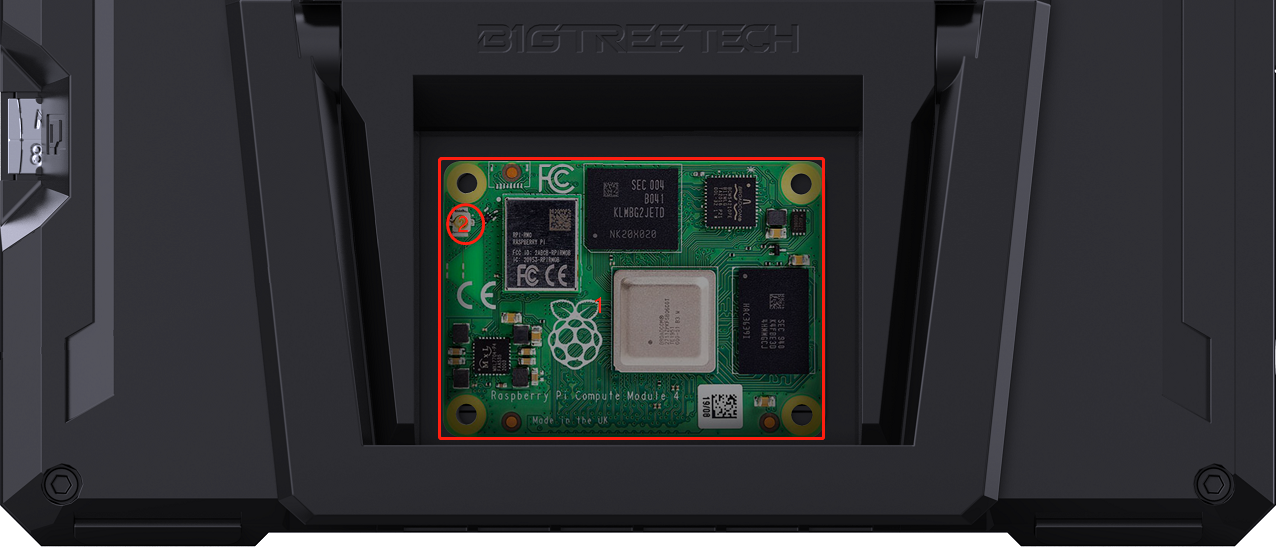
4.Use tweezers to gently lift the antenna connector highlighted in 1 to disconnect it from CB1.
Then remove CB1.
5.Align the BTB connectors of the Pad 7 and CM4.
Press down on the CM4 until it is firmly seated in place. Please note that CM4 should be installed in the direction shown in the figure below.
Plug the antenna connector into the port highlighted in 2.
6.Cover the heatsink back onto the CM4.
Use a 2.0mm hex key to tighten the four M2.5 x 10 socket head cap screws in a clockwise direction.
7.Refer to the figure below, and slide the switch of USB-Choose and CS-Choose to the CM4 position.

Note:White blocks represent the current positions of the slide switch.
8.Cover the bottom cover back onto the Pad 7.
Use a 1.5 mm hex key to fix the bottom cover in place using the two M2.5 x 3 flat head countersunk screws.
9.Finally, insert the TF card containing the Raspberry Pi Imager software into the designated card slot, and then power the Pad 7 on.
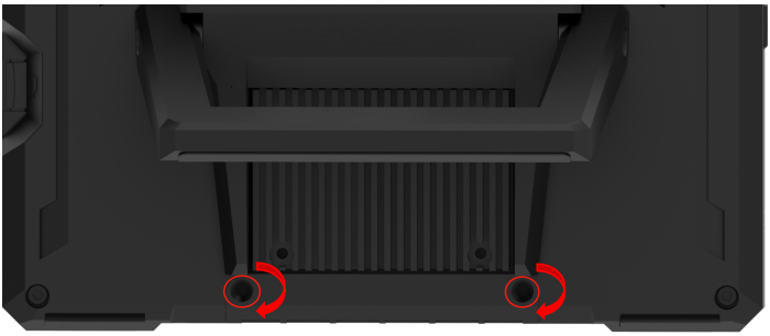
To Remove the Bracke
1.Use a 3.0 mm hex key to loosen the two screws that secure the bracket in a counterclockwise direction.
2.Once the screws have been removed, gently pull the bracket away from the Pad 7.
Software Configuration
To Work with a CB1
Download OS Image
Only the OS image provided by BIGTREETECH is compatible with the CB1
It is recommended to use the CB1_Debian11_Klipper_xxxx.img.xz image file that contains "Klipper" in its name, rather than the image file with "minimal" in its name.
To Download and Install the Writing Software
Raspberry Pi Imager: https://www.raspberrypi.com/software/
BalenaEtcher: https://www.balena.io/etcher/
Note: You can choose to use either Raspberry Pi Imager or BalenaEtcher to write the OS image to the microSD card.
Start to Write OS
Using Raspberry Pi Imager
For details, please click:https://bigtreetech.github.io/docs/Software%20Installation.html#write-os-image
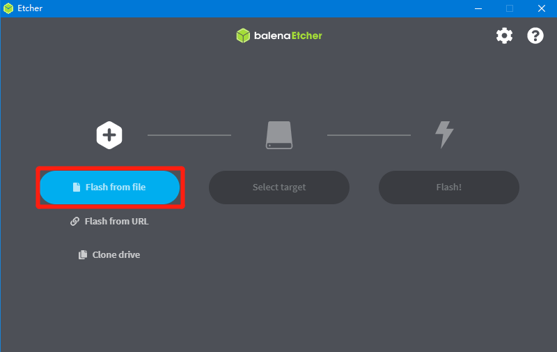
Using BalenaEtcher
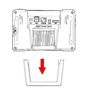
1.Insert a microSD card into your computer via a card reader.
2.Select the downloaded image.
3.Select the microSD card and click "WRITE" (WRITE the image will format the microSD card. Be careful not to select the wrong storage device, otherwise the data will be formatted).
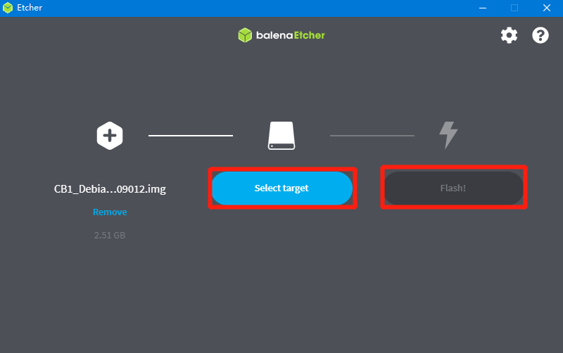
4.Wait for the writing process to complete.

System Settings
Setting Description
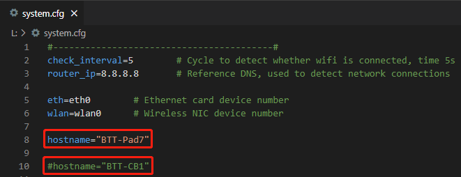
In the configuration file, the '#' symbol represents a comment, and the system ignores any content that appears after the '#' symbol. As shown in the figure below:
#hostname="BTT-CB1" - This line is ignored by the system, and it is equivalent to not being present.
hostname="BTT-Pad7" - This line is recognized by the system, and the hostname is set to "BTT-Pad7".
Setting up WiFi
Note: If you are using a wired connection, skip this step.
After the OS image has been burned onto the microSD card, a FAT32 partition that is recognized by the computer will be created on the card. Under this partition, there will be a configuration file named "system.cfg". Open this file, and replace WIFI-SSID with the actual name of your WIFI network, and PASSWORD with your actual WIFI password.

Pad 7 Settings
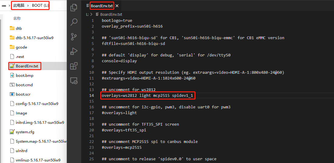
Open the "BoardEnv.txt" configuration file, and set the following parameters:
ws2812:Enables the RGB light located in the upper right corner of the Pad 7.
light:Enables the PWM function for the LCD backlight.
mcp2515:Enables the MCP2515 SPI to CAN, which provides CAN functionality on the Pad 7.
spidev1_1:Enables the spidev1_1 to the system user space, allowing the Pad 7's SPI port to connect to an ADXL345 accelerometer module.
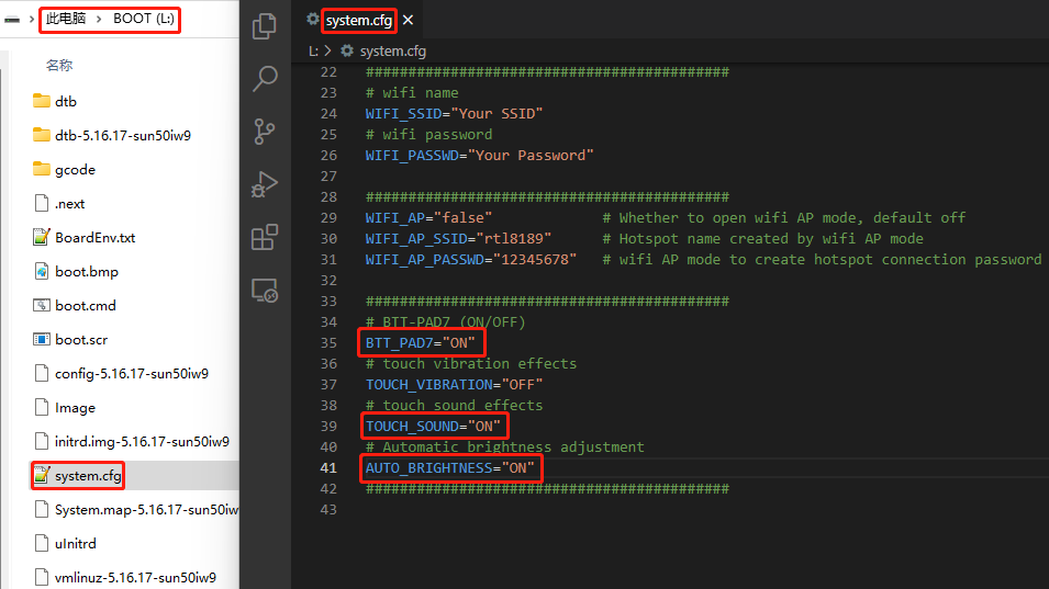
Open the "system.cfg" configuration file and modify the following settings:
BTT_PAD7="ON" # Enables Pad7 related scripts.
TOUCH_VIBRATION="OFF" # OFF: Disables vibration feedback. ON: Enables vibration feedback.
TOUCH_SOUND="ON" # OFF: Disables sound feedback, ON: Enables sound feedback.
AUTO_BRIGHTNESS="ON"# OFF Disables automatic backlight adjustment based on ambient light. ON: Enables automatic backlight adjustment based on ambient light.
Note: The TOUCH_VIBRATION and TOUCH_SOUND settings require KlipperScreen support. If you want to use the touch feedback function, please follow the steps below to set up KlipperScreen.
Setting up Touch Feedback
Since KlipperScreen does not provide API interfaces for touch feedback, it is necessary to replace the official KlipperScreen with our modified version of KlipperScreen. Follow the steps below to replace the KlipperScreen:
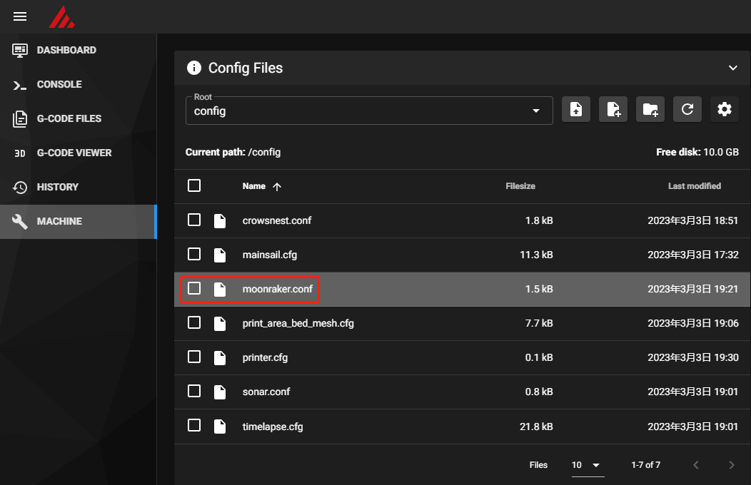
1.Open the moonraker.conf file in Mainsail.
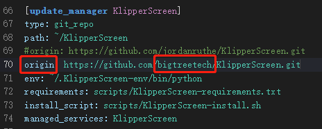
2.Change the origin of KlipperScreen from the official
https://github.com/jordanruthe/KlipperScreen.git to: https://github.com/bigtreetech/KlipperScreen.git
If you want to use the official version instead of BigTreeTech's, simply change the link back.
3.Click the refresh button in the upper right corner of the Update Manager, then Hard Recovery KlipperScreen.
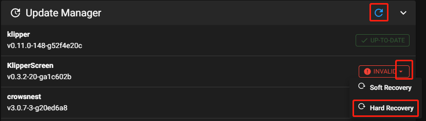
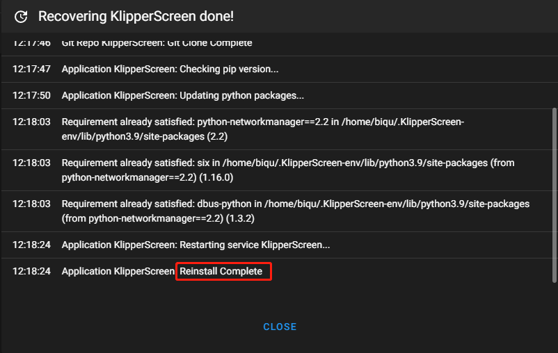
4.Wait for the update to complete.
Setting up SPI to CAN
As explained in "Pad 7 Settings" section, set the overlays to include mcp2515 to enable the CAN functionality automatically after booting.
Setting up ADXL345
As explained in "Pad 7 Settings" section, set the overlays to include spidev1_1. After booting, the system user space should load spidev1.1. Add the following configuration to the printer.cfg file to use the ADXL345:
[adxl345]
cs_pin: CB1:None
spi_bus: spidev1.1
axes_map: z,y,-x  # Modify according to the actual orientation of the ADXL345 installed on the printer.
To Work with a CM4
We recommend using the OS image released by Mainsail:
https://github.com/mainsail-crew/MainsailOS/releases
The steps for burning the system are the same as with CB1.
Setting up Backlight
Note: The backlight IO of CM4 does not have PWM function, so it can only be set to maximum brightness.
1.Remove "console=serial0,115200" from /boot/cmdline.txt file (if it exists).
2.Remove enable_uart=1 from /boot/config.txt file (if it exists).
3.Add the following lines to /boot/config.txt file:
Setting up Resolution and Touch
1.Add the following lines to /boot/config.txt file to specify the HDMI output resolution:
Some versions of the system disable USB by default to save power. To enable USB, add the following line to /boot/config.txt file. Also, Pad 7's touch function uses the USB HID protocol, so USB needs to be enabled.
Setting up SPI to CAN
Add the following lines to /boot/config.txt file:
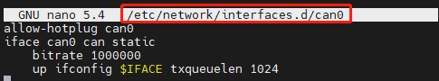
Execute sudo nano /etc/network/interfaces.d/can0 in the SSH terminal to edit the can0 file and check if the contents of the file are correct. The bitrate 1000000 represents the baud rate of the CAN bus and should be consistent with the settings in Klipper.
Setting up ADXL345
Add dtparam=spi=on to /boot/config.txt file. After booting, the system user space should load spidev0.1. Add the following configuration to the printer.cfg file to use the ADXL345:
[adxl345]

cs_pin: CM4:None

spi_bus: spidev0.1

axes_map: z,y,-x  #  Modify according to the actual orientation of the ADXL345 installed on the printer.
FAQ
CAN bus Not Working
1.Check the CS-Choose switch inside Pad 7. When used with CB1, it should be set to the CB1 position, and when used with CM4, it should be set to the CM4 position.


Note:Whiteblocksrepresentthecurrentpositionsoftheslideswitch.
Note:White blocks represent the current positions of the slide switch.
2.Check the H and L wiring of the CAN bus connection according to the “Connection between Pad7, EBB36, and ADXL345” section of this manual.
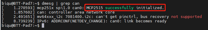
3.In the SSH terminal, execute the command "dmesg | grep can". The response should be "MCP2515 successfully initialized".
4.In the SSH terminal, execute the command "sudo nano /etc/network/interfaces.d/can0" to edit the can0 file and check if the content of the file is normal. The bitrate 1000000 represents the CANbus baud rate, which should be consistent with the setting in Klipper.

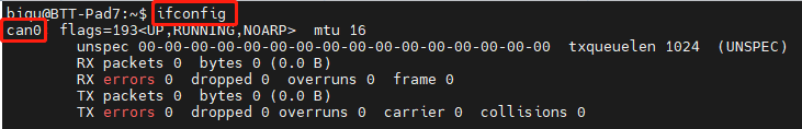
5.In the SSH terminal, execute the command "ifconfig" to check if the can0 service exists. A normal situation is shown in the figure.
ADXL345 Not Working
1.Check the CS-Choose switch inside Pad 7. When used with CB1, it should be set to the CB1 position, and when used with CM4, it should be set to the CM4 position.


2.Check the wiring sequence of the SPI port according to the “Connection between Pad7, EBB36, and ADXL345” section of this manual.
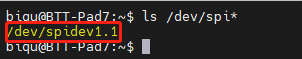
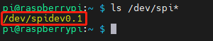
3.In the SSH terminal, execute the command "ls /dev/spi*" to check if CB1 has a device named "spidev1.1" and if CM4 has a device named "spidev0.1".
Cautions
- Do not attempt to hot-swap the TF card. Make sure it is properly inserted before powering on the device.
- We advise customers not to disassemble the device as they may not be familiar with the internal structure, which can lead to internal circuit breakdown. Any problems caused by disassembling will not be covered by compensation.
- If you need to replace the core board, follow the replacement steps provided (see "To Replace CB1 with CM4" section).
- When wiring the SPI interface to the expansion module, pay close attention to the silkscreen to avoid short circuits.
If you require additional resources for this product, please visit https://github.com/bigtreetech/ to find them. If you cannot find the resources you need, please reach out to our after-sales support team for assistance.
If you encounter any other issues while using this product, please don't hesitate to contact us. We will provide careful answers to your inquiries. We also welcome any feedback or suggestions you may have about our products, and we will consider them carefully. Thank you for choosing BIGTREETECH. Your support means a lot to us!
Product Purchase Link
Purchase Link:
https://biqu.equipment/products/bigtreetech-pad-7
If you have any issues with the product, please submit a support ticket.
https://biqu3d.com/pages/submit-a-ticket
Navigation:
BIQU Official Website: http://biqu3d.com
BIGTREETECH Official Website: http://bigtree-tech.com
Online Store: https://biqu.equipment
BIGTREETECH Official Group: https://www.facebook.com/groups/bigtreetech
Discord: https://discord.gg/hhZsV7zk
Reddit: https://www.reddit.com/r/BIGTREETECH/