ADXL345 V2.0

Product Profile
BIGTREETECH ADXL345 V2.0 is a module for printer resonance compensation. It can communicate through USB, greatly simplifying wiring.
Product Link: BIGTREETECH Official Website
Features Highlights
- The board has a reserved BOOT button for easy firmware updates.
- Reserved solder points enable users to customize wiring easily.
- The USB port has an added ESD protection chip to prevent the MCU from being damaged by static electricity through the USB.
Specifications
| Dimensions | 33.25 x 15.5mm |
|---|---|
| Installation Dimensions | See BIGTREETECH ADXL345 V2.0-SIZE.pdf for details. |
| Microprocessor | RP2040 Dual ARM Cortex-M0+ @ 133MHz |
| Input Voltage | DC 5V |
| Logic Voltage | DC 3.3V |
| Communication with PC | USB2.0 |
| Sensor | ADXL345 |
| Sensor Communication | 4Line SPI |
| Resolution | Up to 3.9mg/LSB. |
| Output Data Rate | 0.1-3200Hz |
| Sensor Operating Temperature Range | -40℃ to +85℃ |
Firmware Support
This product currently only supports Klipper firmware.
Dimensions

Peripheral Interface
Pin Description

Interface Introduction
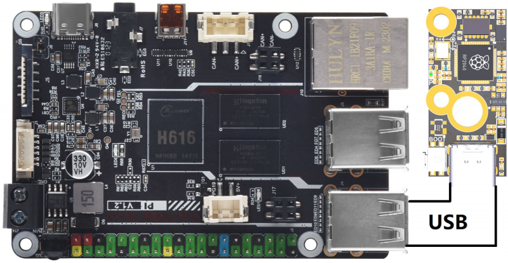
Connecting to BTT Pi V1.2 (Type-C)
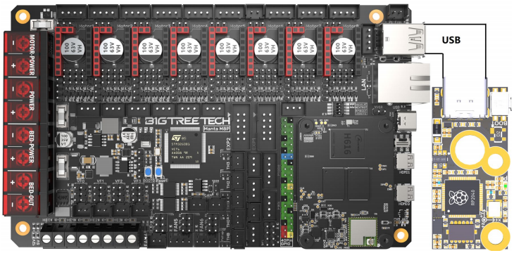
Connecting to Manta M8P (Type-C)
Connecting to Manta M8P (Soldering Wires)

Klipper Firmware
Compiling Klipper Firmware
- Connect to CB1/Raspberry Pi via SSH and enter the following commands:
Configure the firmware as shown in the provided image (update Klipper firmware to the latest version if options are not available).

-
After configuration, press q to exit, and select Yes when prompted to save.
-
Enter make to compile the firmware. The resulting klipper.bin file will be in the home/pi/klipper/out folder. This can be directly downloaded to your computer from the SSH software's left panel.

Firmware Update via DFU
Raspberry Pi or CB1 update via DFU.
Hold the Boot button and connect the board to Raspberry Pi/CB1 via Type-C cable to enter DFU mode.
Enter lsusb in the SSH terminal to query the DFU device ID.

Using command below to navigate to the Klipper directory:
Then using command below to flash DFU device:
After flash firmware into ADXL345. It can using command below to find serial id of device:
Note
to query the device's Serial ID (only applicable for USB communication, not for CANBus).
Note
For USB communication, you don't need to press the Boot button for subsequent updates. Enter the following command to flash the firmware
replacing /dev/serial/by-id/<serial-id> with the actual ID found in the previous step
Configuring Klipper
Info
Download the sample-bigtreetech-adxl345-v2.0.cfg config file from GitHub ADXL345
Upload to the Configuration Files.

Add section below into printer.cfg
Then set the correct ID number for your board.
!!! tip Configure the module's functions according toADXL345 Config Reference
The axes_map parameter needs to be set according to the direction of the module installation and the movement direction of the printer. The first parameter represents the direction of the accelerometer module corresponding to the axis when the printer's X-axis moves in the positive direction (the silk screen on the module shows the direction of each axis of the module), and the second parameter represents the direction of the accelerometer when the Y-axis moves in the positive direction.
Tip
After configuring and installing the module and successfully connecting to the printer, you can start the resonance compensation test.
In Mainsail's Console, enter the following command to start X axis calibration:
Enter the following command to start Y axis calibration:
After calibration is complete, follow the prompts and enter SAVE_CONFIG to save the calibration parameters.
Tip
After the resonance compensation test, the ADLX345 module can be removed. The module configuration needs to be commented out in the printer.cfg file, otherwise the printer will fail to start if it cannot find the module. Comment out the module configuration by adding # in front of the config file name:
Assembly
Warning
Avoid overtightening screws during installation to prevent damage.
Example using the Voron StealthBurner:
Method 1:
Install on the side bracket with the dual holes (matches official spacing).

Method 2:
Use screws through the PCB and rubber ring on the heater block as shown.
