DZ01

Product Profile
The BIGTREETECH DZ01 is a powerful motherboard featuring the Allwinner H616 SoC, a quad-core Cortex-A53 @1.5 GHz, with 1GB DDR3L RAM, and support for high-performance Klipper running. It includes a 32-bit RP2040 MCU for precise multi-axis motion control, onboard TMC2209 drivers, Wi-Fi connectivity, and 4K HDMI output, making it an all-in-one solution for your 3D printing projects.
Feature Highlights
- MCU: 32-bit ARM Cortex-M0+ series RP2040, running at 133MHz;
- SoC: Allwinner H616, Quad-core Cortex-A53 @1.5GHz;
- GPU: Mali G31 MP2, supports OpenGL 3.2;
- RAM: 1GB DDR3L SDRAM;
- Display Output: HDMI 2.0A, supports 4K monitors;
- Two USB 2.0 ports;
- Serial Port Output;
- Networking: 100Mbps Ethernet + 100Mbps Wi-Fi;
- Contains a TPS5450-5A power chip which supports DC12/24V power input. This chip provides an output current of up to 5A, peaking at 6A;
- A reserved BOOT button within the motherboard allows users to update the bootloader using the DFU mode;
- A specially designed circuit on the motherboard protects the signal coming back from the thermistor, preventing MCU damage from shorted heated beds and heater cartridge connections;
- Users can upgrade the MCU firmware via an SD card, or update the MCU firmware through DFU using the make flash command in Klipper;
- Includes specific interfaces that are reserved for Filament Detection, Auto Power-Off, BLTouch, RGB, etc.
- High-performance MOSFETs assist in reducing heat generation by controlling the flow of electrical current;
- Includes replaceable fuses;
- Proximity Switch Interface: Reserved;
- SPI Expansion Interface: Reserved for connecting external accelerometers for Klipper input shaping.
Specifications
- Dimensions: 80mm*125mm
- Mounting Dimensions: For details, please refer to BIGTREETECH DZ01.pdf
- SoC: ALLWINNER H616, Quad-core Cortex-A53 @1.5GHz
- MCU: 32-bit ARM Cortex-M0+ series RP2040 with a clock speed of 133MHz
- Driver Input Voltage: 24V
- Motherboard Input Voltage: VIN=DC12V or DC24V
- Heated Bed Input Voltage: BED IN=DC12V or DC24V
- Logic Voltage: DC3.3V
- Heating Interface: Heating Interface: Heated Bed (HB), Heater Cartridge (HE0, HE1)
- Max Heated Bed Output Current: 10A, peak 12A
- Max Heater Cartridge Output Current: 5.5A, peak 6A
- Fan Interfaces: 2-pin PWM Fans (FAN0, FAN1, FAN2), Voltage fixed at 24V
- Max Fan Output Current: 1A, peak 1.5A
- Total Current for Heater Cartridge+Drivers+Fans: Less than 12A
- Expansion Interfaces: BLTouch (Servos, Probe), PS-ON, Fil-DET, RGBx2, SPI, USB 2.0 x2, HDMI0, SOC-Card, Wi-Fi
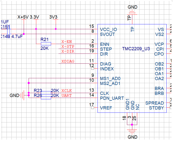
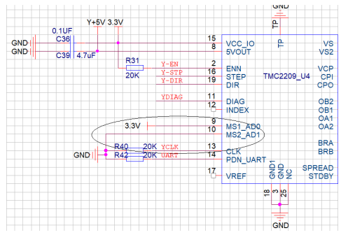
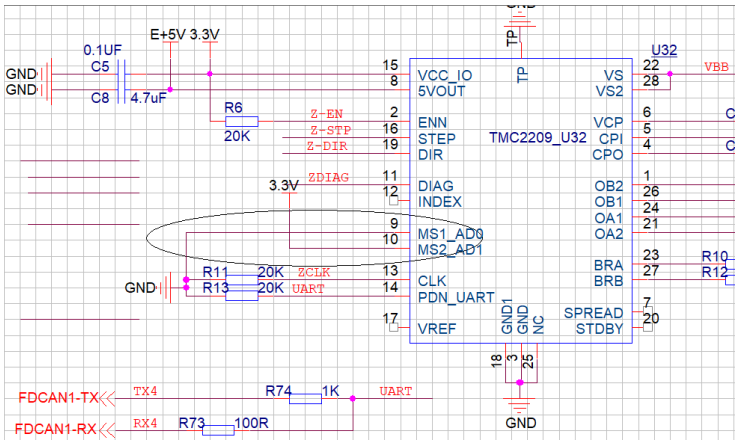
- Motor Drivers: TMC2209 x4
- Driver Modes: SPI, UART, STEP/DIR
- Motor Interfaces: Motor X, Motor Y, Motor Z, Motor E0, Motor E1 (5 total)
- Temp Sensor Interfaces: 3x 100K NTC
- Display: SPI Touchscreen
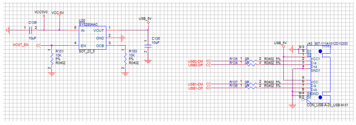
- PC Communication: Type-C
- Supported Kinematics: Cartesian, Delta, Kossel, Ultimaker, CoreXY
- Recommended Slicer/Console: Cura, Simplify3D, Pronterface, Repetier-host, Makerware
Dimensions

Peripheral Interface
Interface Diagram

Interface Introduction
USB Power Supply
The power light on the upper left corner of the MCU turns red when DZ01 is powered on, indicating a normal power supply. The VUSB power select pin needs to be shorted by placing the jumper over the pin, however this is only necessary when a USB is required to supply power to the board.
SPI Interface
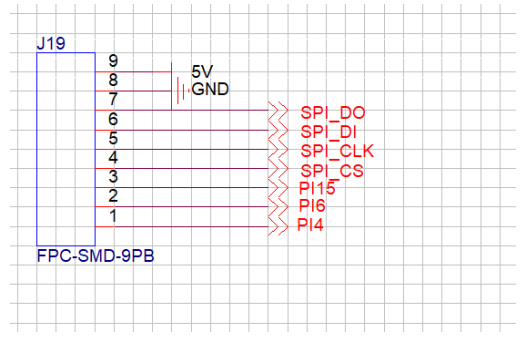
- SPI_DO H616-PH8
- SPI_DI H616-PH7
- SPI_CLK H616-PH6
- SPI_CS H616-PI14
- SPI_RES H616-PI15
- SPI_SDA H616-PI6
- SPI_SCL H616-PI4
Serial Port Interface
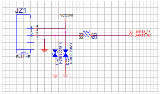
- UART3_TX H616-PI4 PI9
- UART3_RX H616-PI4 PI10
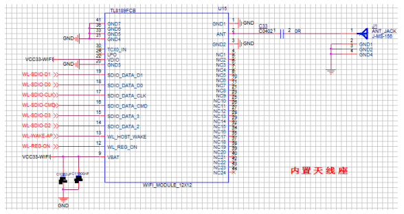
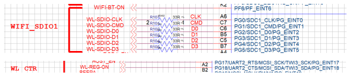
Wi-Fi Interface
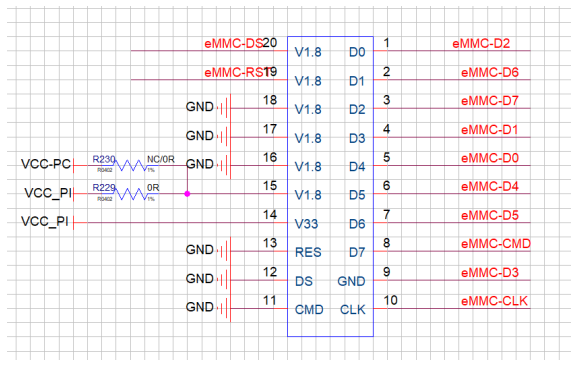
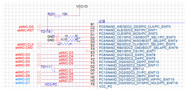
EMMC Interface

LED Interface


- J41 EN H616-PG6
- J40 EN H616-PG7
- J23 PWM RP2040- GPIO6
- J24 PWM RP2040- GPIO5
CN16 Interface
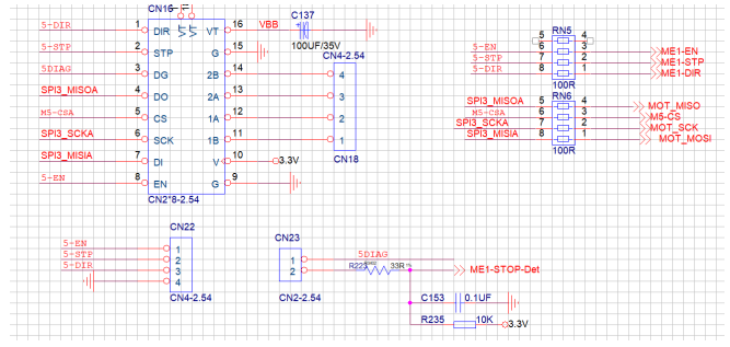
- STOP H616-PI8
- EN H616-PI12
- STP RP2040- GPIO2
- DIR RP2040- GPIO3
- MISO RP2040- GPIO16
- CS RP2040- GPIO24
- SCK RP2040- GPIO18
- MOSI RP2040- GPIO19
MOTOR X Interface
- STOP H616-PI1
- EN H616-PI3
- STP RP2040- GPIO15
- DIR RP2040- GPIO14
- UART RP2040- GPIO0 TX/GPIO1 RX
MOTOR Y Interface
- STOP H616-PI5
- EN H616-PI0
- STP RP2040- GPIO13
- DIR RP2040- GPIO12
- UART RP2040- GPIO0 TX/GPIO1 RX
MOTOR Z Interface
- STOP H616-PI13
- EN H616-PI7
- STP RP2040- GPIO10
- DIR RP2040- GPIO9
- UART RP2040- GPIO0 TX/GPIO1 RX
MOTOR E0 Interface

- STOP H616-PI1
- EN H616-PI2
- STP RP2040- GPIO8
- DIR RP2040- GPIO7
- UART RP2040- GPIO0 TX/GPIO1 R
MOTOR E1 Interface
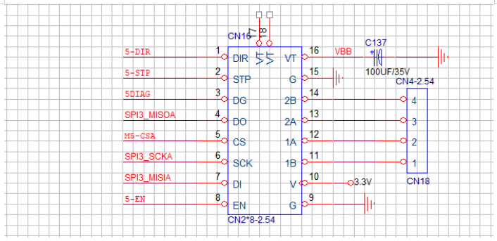
- EN H616-PI12
- STP RP2040- GPIO2
- DIR RP2040- GPIO3
- MISO RP2040- GPIO16
- CS RP2040- GPIO24
- SCK RP2040- GPIO18
- MISI RP2040- GPIO19
Other Interfaces
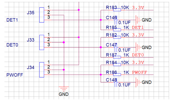
- DET1 H616-PG11
- DET0 H616-PG16
- POWER RP2040- GPIO25
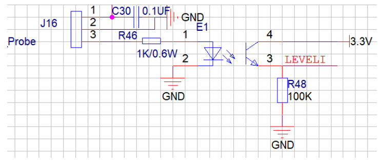
- LEVELI RP2040- GPIO20
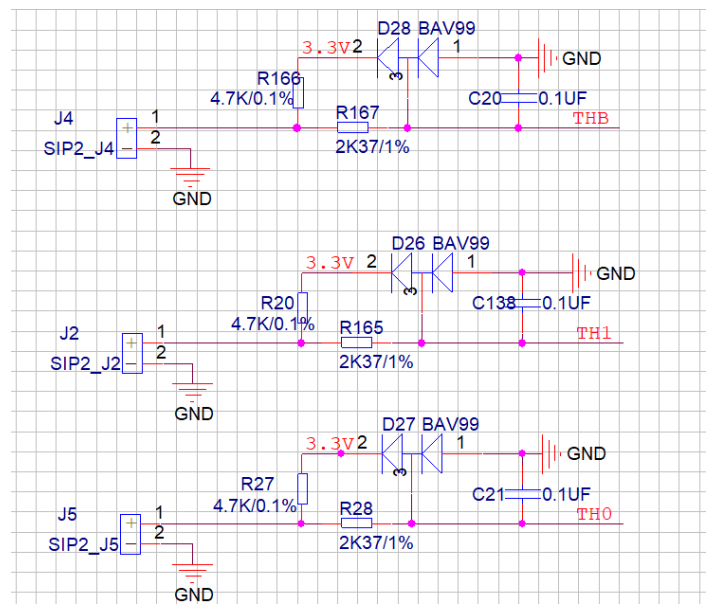
- THB RP2040- GPIO28
- TH1 RP2040- GPIO27
- TH0 RP2040- GPIO26
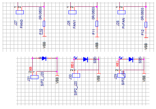
- FAN0 RP2040- GPIO29
- FAN1 RP2040- GPIO4
- FAN2 RP2040- GPIO11
- HB RP2040- GPIO23
- HE1 RP2040- GPIO22
- HE0 RP2040- GPIO21
Buzzer Interface

BEEP H616-PG19
USB Power Supply Interface
HOST_EN H616-PG17
Battery Power Supply Interface
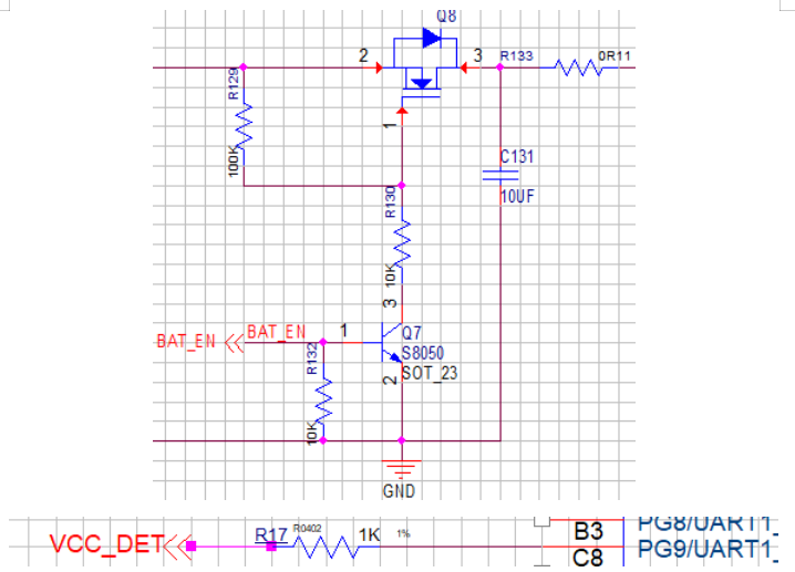
- BAT_EN H616-PG14
- VCC_DET H616-PG9
- (Note: H616 enters saved data and shuts down when PG9 detects 0)
Serial Communication and Firmware Flashing Instructions

- To flash EMMC on H616, set switch to position 1 and hold BOOT0.
- For serial output on H616, set switch to position 2.
- To flash RP2040, set switch to position 3, and set switch 2 to PC-RP2040.
- For communication between RP2040 and H616, set switch 2 to H616-RP2040.