KRAKEN V1.0/V1.1
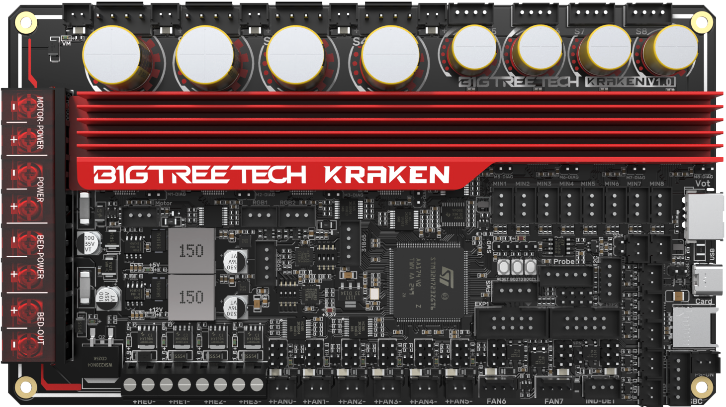
Product Profile
BIGTREETECH Kraken V1.0 is a 32-bit motherboard for large printers. It comes with onboard high-voltage, high-current stepper motor drivers, significantly simplifying the connection between the motherboard and high-voltage drivers and saving space in the chassis. The board uses silkscreened ID design with an ID-design heat sink for aesthetics and practical cooling.
Features Highlights
- Utilizes a 32-bit ARM Cortex-M7 series STM32H723ZGT6 MCU with a main frequency of 550 MHz.
- TPS5450-5A power chip, supporting DC12/24V power input. This chip provides an output current of up to 5A, peaking at 6A, perfectly supporting Raspberry Pi power supply.
- The motherboard has a reserved BOOT button, allowing users to update the bootloader via DFU mode.
- The thermistor circuit is protected to prevent MCU damage from shorted heated bed and heater cartridge connections;
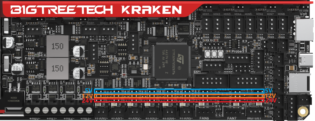
- Selectable voltage (24V, 12V, 5V) for PWM fan, eliminating the need for external voltage conversion modules, thereby reducing the likelihood of motherboard damage.
- Onboard two MAX31865 modules, supporting dual PT thermocouples and compatible with two or four-wire PT100/PT1000, facilitating DIY usage for customers.
- Firmware can be upgraded via MicroSD card or through the Klipper's
make flashcommand via DFU. - Onboard 8 TMC2160 drivers in SPI mode with DIAG function pins; simply plug and unplug jumpers for easy use.
- Reserved interfaces for Filament Detection, Auto Power-Off, Probe, RGB, I2C, Servo, EXP1+EXP2, CAN, UART (SBC), and USB A power output.
- High-performance MOSFETs to reduce heat generation.
- Replaceable fuses for easy replacement.
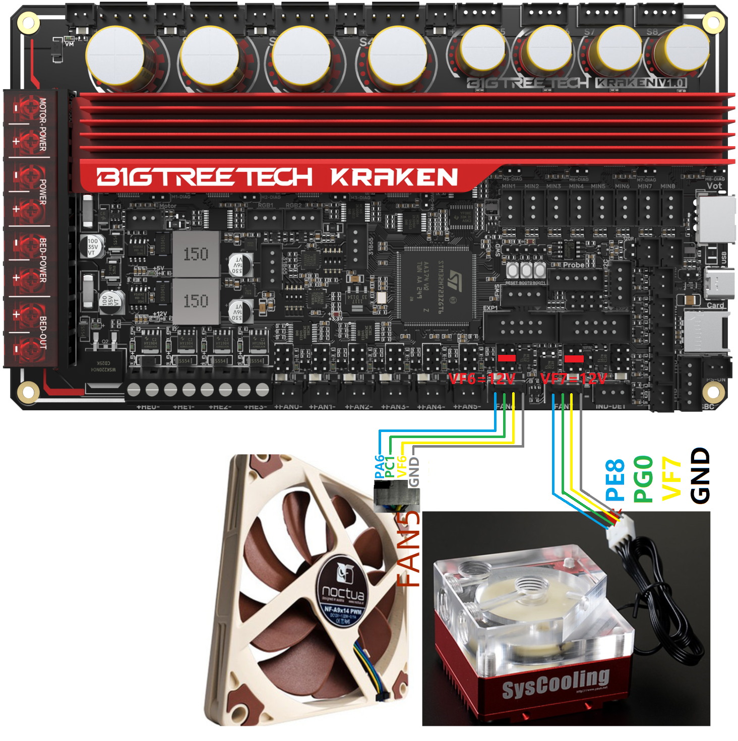
- 2x 4-pin fan interfaces with selectable voltages of 24V, 12V, and 5V, also suitable for water cooling setups.
- Onboard proximity switch port, supports NPN and PNP types, 24V, 12V, 5V voltage selectable;
- Reserved SPI interface for connecting an accelerometer for Klipper resonance compensation.
- External DC12V powers the MOSFET control power for TMC2160, reducing driver output impedance and chip heat generation.
Specifications
| Specifications | |
|---|---|
| MCU | ARM Cortex-M7 STM32H723ZGT6 550MHz |
| Driver Input Voltage | HV (24-60V) |
| Motherboard Input Voltage | DCIN = DC12V or DC24V |
| Heated Bed Input Voltage | BED IN = DC12V or DC24V |
| Logic Voltage | DC3.3V |
| Heating Interface | Heating Interface: Heated Bed (HB), Heater Cartridge (HE0, HE1, HE2, HE3) |
| Max Heated Bed Output Current | 10A, peak 11A |
| Max Heater Cartridge Output Current | 6A, peak 6.5A |
| Fan Interfaces | 6x 2-pin PWM Fans (FAN0, FAN1, FAN2, FAN3, FAN4, FAN5), 2x 4-pin PWM Fans (FAN6, FAN7), 5x Always-On Fan, PWM Fans Voltage (5V, 12V, 24V) Selectable |
| Max Fan Output Current | 1A, peak 1.5A |
| Total Current for Heater Cartridge + Fans | Less than 14A |
| Motherboard Max 5V Output Current | 5A (peak 6A) |
| Motherboard Max 12V Output Current | 5A (peak 6A) |
| Expansion Interfaces | Probe (Servos, Probe), Servo, Filament Sensor, PS-ON, I²C, RGBx2, SPI, SBC (UART), EXP1+EXP2, CANx2, PT100/PT1000x2, USB-A 5V Power, Endstop Portx8, etc. |
| Motor Drivers | Onboard TMC2160, support 24-60V, V1.0:Max 8A driving current for S1-S4(Rsense=22mR), V1.1:Max 4.7A driving current for S1-S4(Rsense=50mR), Max 3A for S5-S8(Rsense=75mR) |
| Driver Modes | SPI |
| Motor Interfaces | S1, S2, S3, S4, S5, S6, S7, S8 |
| Temp Sensor Interfaces | 5x 100K NTC, 2x MAX31865 |
| Display | LCD |
| PC Communication | Type-C |
| Supported Kinematics | Cartesian, Delta, Kossel, Ultimaker, CoreXY |
| Recommended Slicer/Console | Cura, Simplify3D, Pronterface, Repetier-host, Makerware |
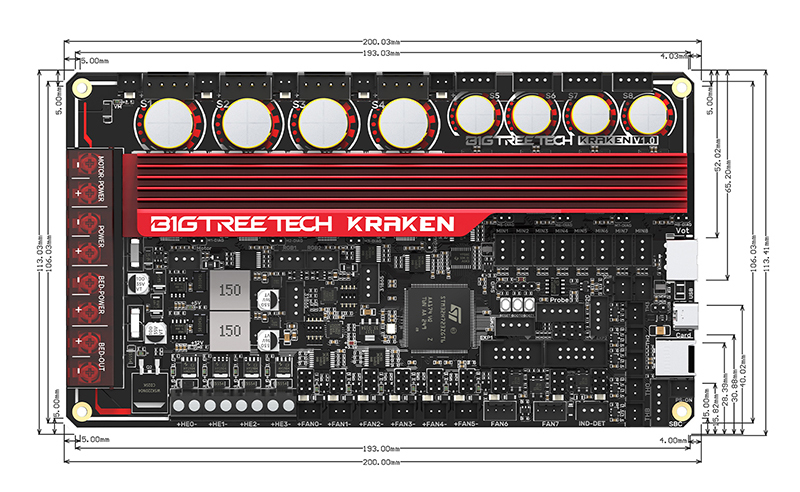
| Dimensions | 200 x 113mm |
| Mounting Dimensions | for details please refer to BIGTREETECH Kraken V1.0-SIZE.png |
Firmware Support
Compatible with Klipper, Marlin, RRF(RepRapFirmware)
Dimensions
Peripheral Interface
Interface Diagram

Pin Description
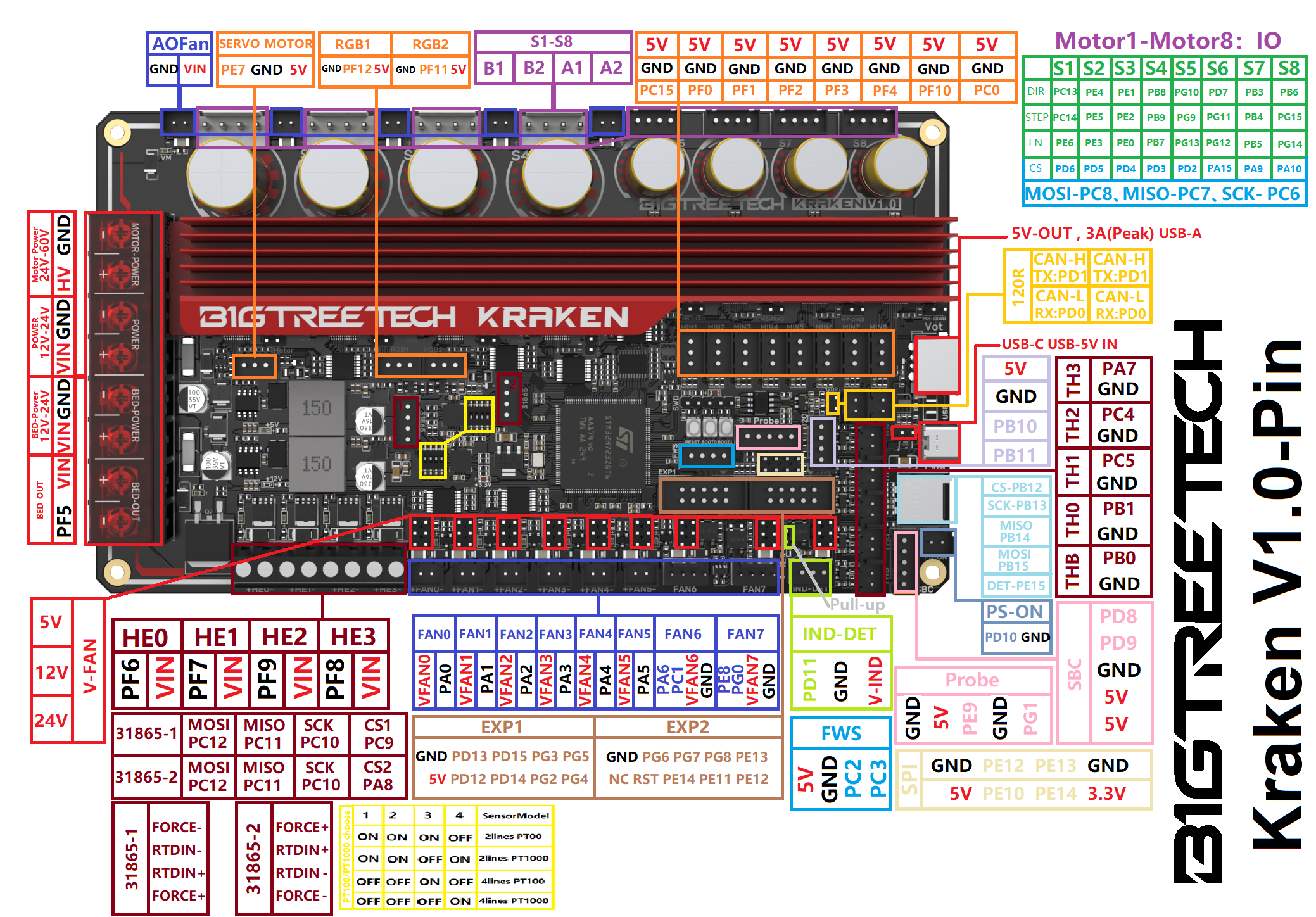
Interface Introduction
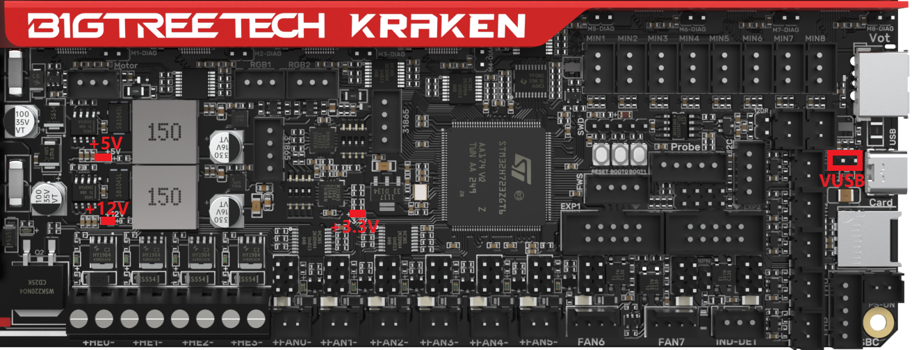
USB Power Supply
When Kraken is powered on, the power indicator light turns red, indicating normal power supply. VUSB is the power select pin which needs to be shorted with a jumper only when supplying power to the board via USB.
Stepper Motor Drivers
Onboard TMC2160 in SPI mode
No jumper is needed to select the mode; directly use the SPI mode. When using Sensorless Homing, plug in the jumper; if not, leave it unplugged. DIAG connection as follows:

PWM Fan Voltage Selection
Set the output voltage to 5V, 12V, or 24V via a jumper. The fan interface output current is 1A.
Warning
Be sure to confirm the supported voltage of the fan before selection to avoid damage for which our company is not responsible.
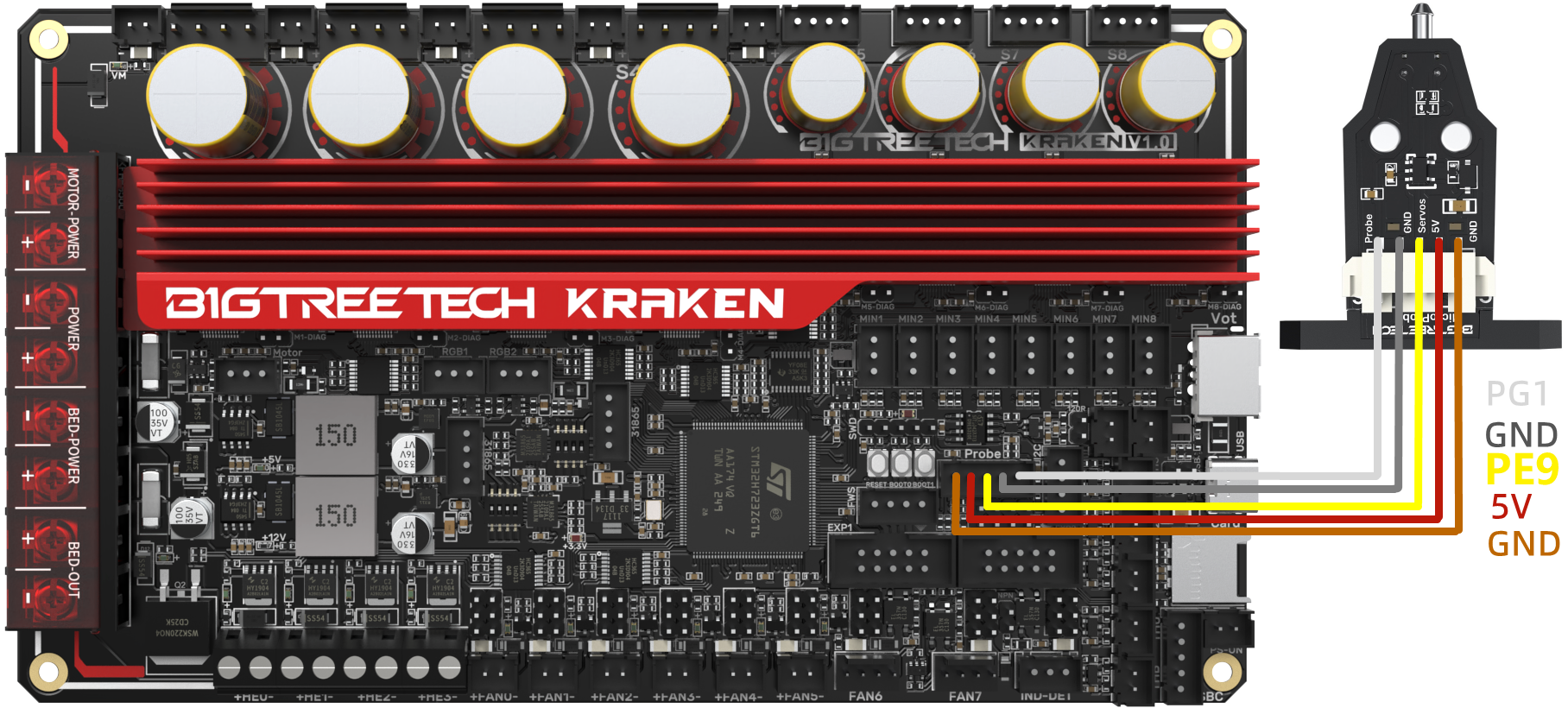
MicroProbe V2.0 Wiring
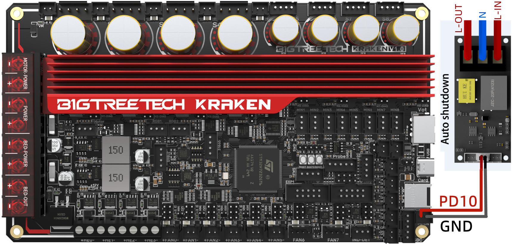
Auto Power Off (Relay V1.2) Wiring
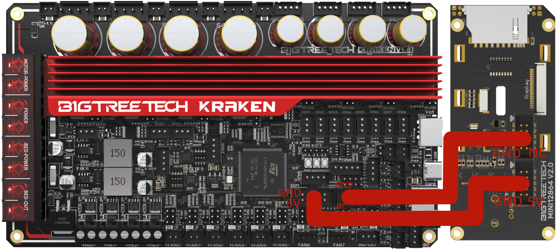
EXP1+EXP2 and MINI12864 V2.0 Display Wiring
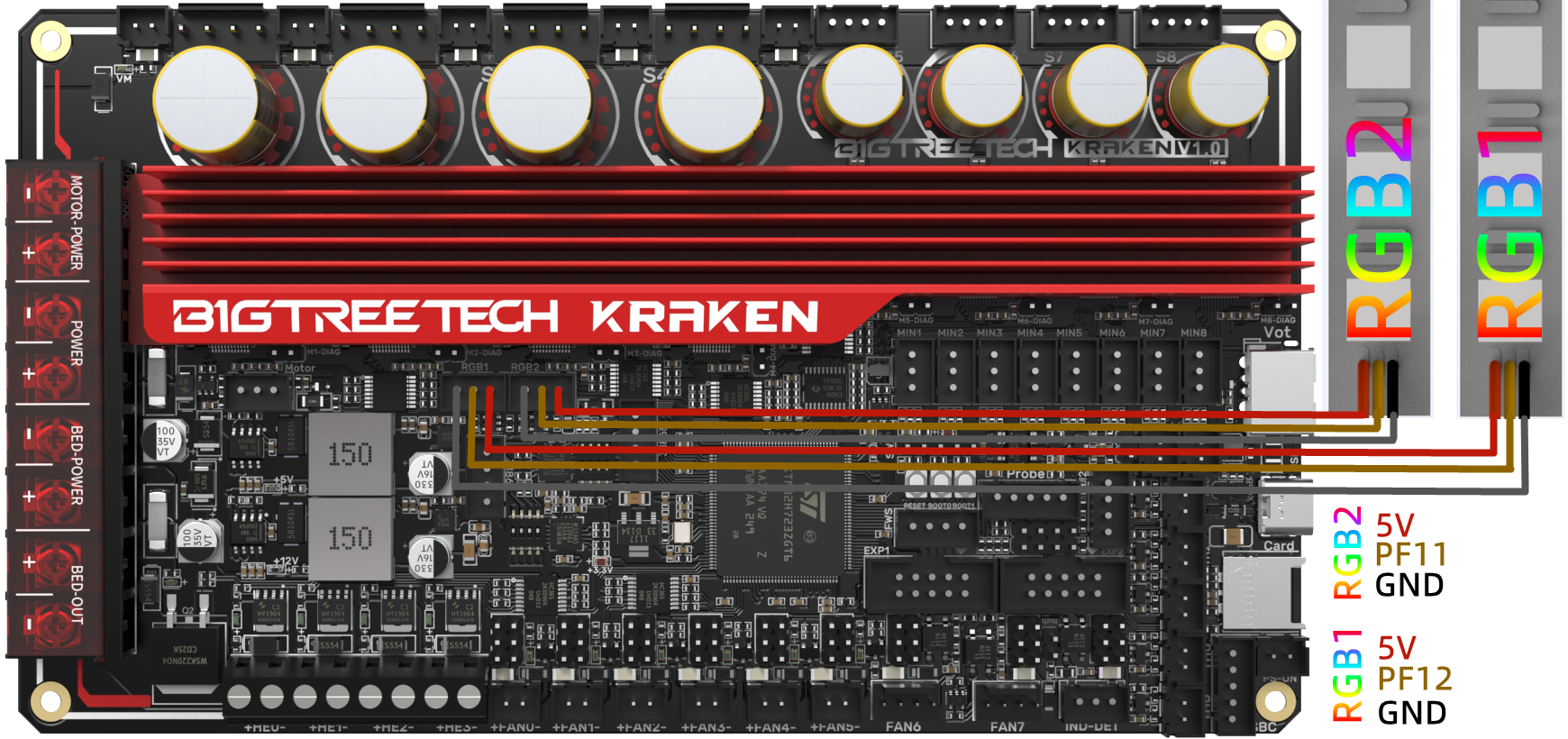
RGB Wiring
Servo Wiring

I2C Wiring (Temperature and Humidity Sensor)

2-pin Fan Connection

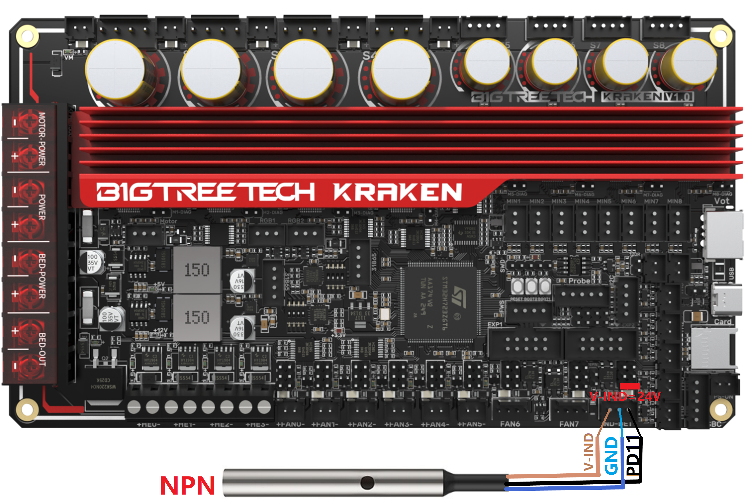
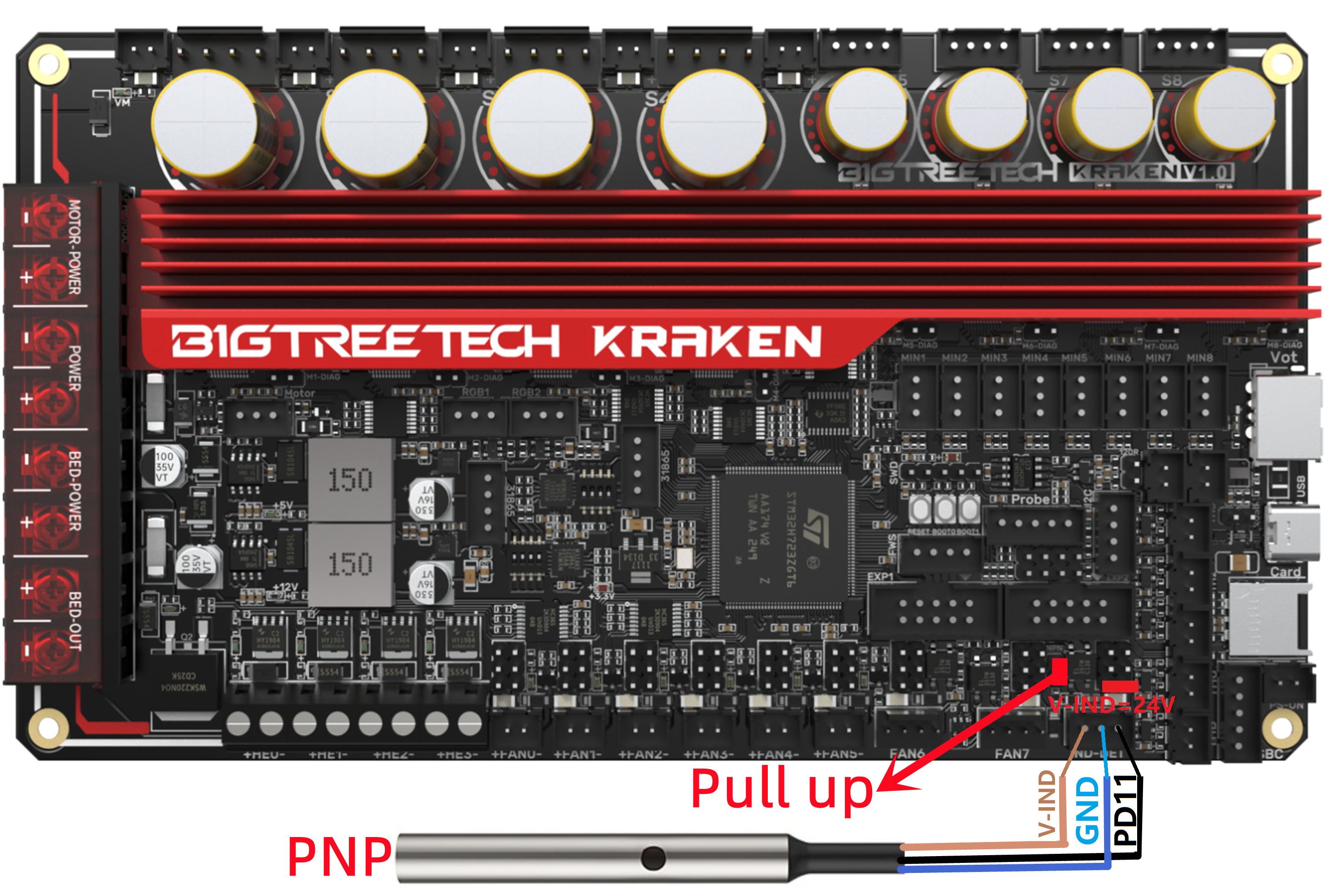
Proximity Switch Connection
Normally open (NPN type), no jumper is required, as shown in the 24V example.
Normally closed (PNP type), a jumper is needed, as shown in the 24V example.
4-pin PWM Fan and Water Cooling Connection (12V example)
Raspberry Pi Connection

Marlin
Install Compiling Environment
https://github.com/bigtreetech/Document/blob/master/How%20to%20install%20VScode%2BPlatformio.md
https://marlinfw.org/docs/basics/install_platformio_vscode.html
Download Marlin Firmware
Get pre-configured firmware source code from our GitHub:
https://github.com/bigtreetech/BIGTREETECH-Kraken
Configure Firmware
Open Marlin Project
You can open Marlin in VS Code in one of several ways:
- l Drag the downloaded Marlin Firmware folder onto the VScode application icon;
- l Use the Open... command in the VSCode File menu;
- l Open the PIO Home tab and click the Open Project button.
Compiling Environment
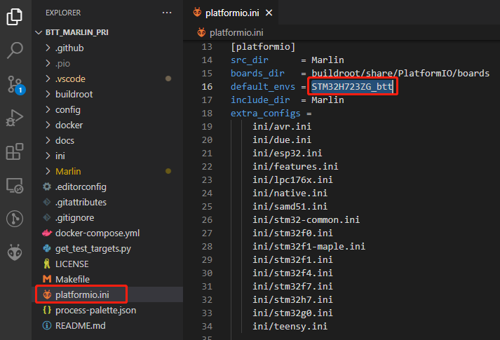
Open platformio.ini file and change default_envs to STM32H723ZG_btt.
Configure Motherboard and Serial Port
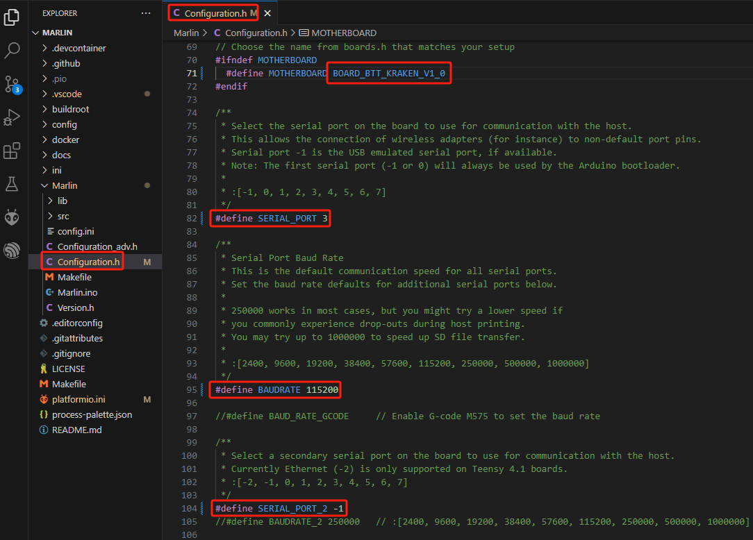
Set MOTHERBOARD as BOARD_BTT_KRAKEN_V1_0
#define MOTHERBOARD BOARD_BTT_KRAKEN_V1_0
#define SERIAL_PORT 3 (Enable SBC serial port)
#define BAUDRATE 115200 (Set baudrate to the same as the communication device)
#define SERIAL_PORT_2 -1 (Enable USB serial port)
The above settings can be enabled as needed.
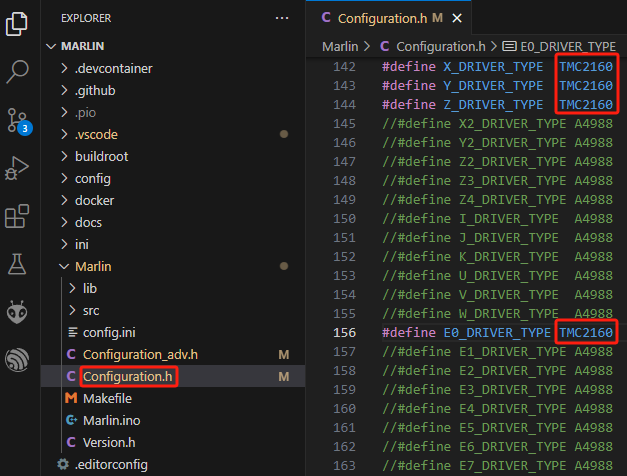
Configure Stepper Driver
Kraken has 8 TMC2160 drivers onboard
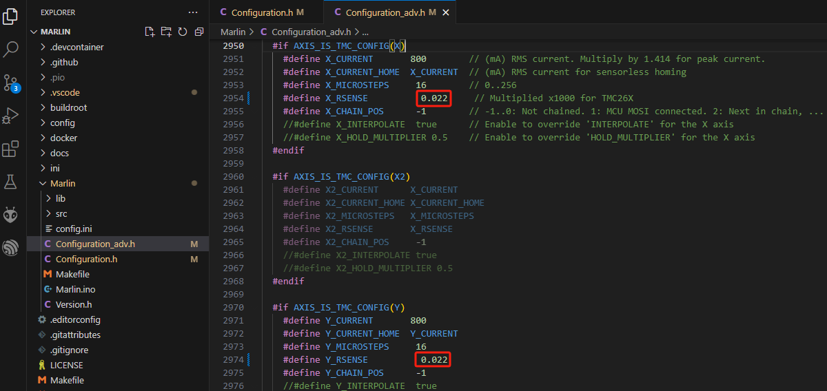
We need to enable TMC_USE_SW_SPI2 in Configuration_adv.h
#define TMC_USE_SW_SPI

V1.0:The Rsense of S1-S4 is 22mΩ, so the firmware needs to be set to 0.022.
V1.1:The Rsense of S1-S4 is 50mΩ, so the firmware needs to be set to 0.05.
The Rsense of S5-S8 is 75mΩ, so the firmware needs to be set to 0.075.
Sensorless Homing
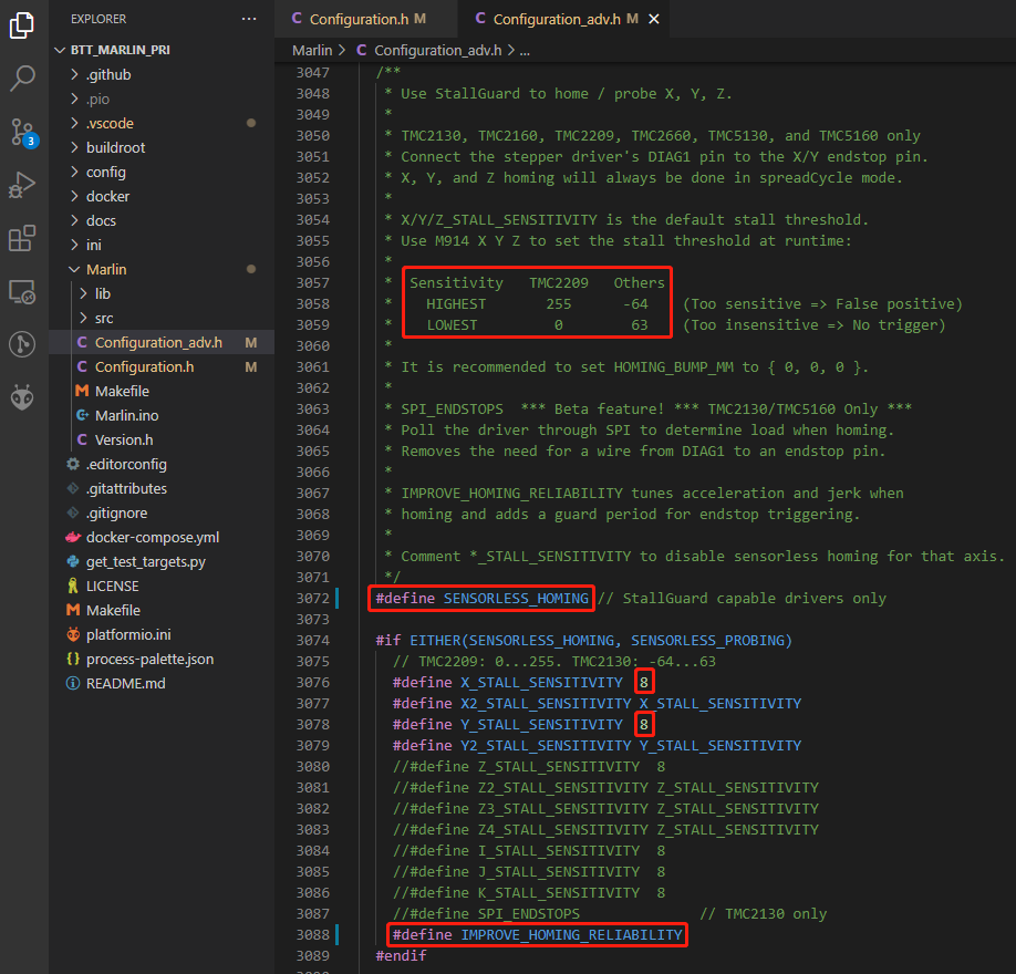
#define SENSORLESS_HOMING // enable sensorless homing
#define xx_STALL_SENSITIVITY 8 // sensitivity setting, TMC2209 range from 0 to 255, higher number results in more sensitive trigger threshold, sensitivity too high will cause endpoint to trigger before gantry actually moves to the end, lower number results in less sensitive trigger threshold, too low of sensitivity will cause endpoint to not trigger and gantrying continue. Other drivers range from 63 to -64, lower numbers result in a more sensitive trigger threshold.
#define IMPROVE_HOMING_RELIABILITY // can be used to set independent motor current for homing moves(xx_CURRENT_HOME) to improve homing reliability.
100K NTC
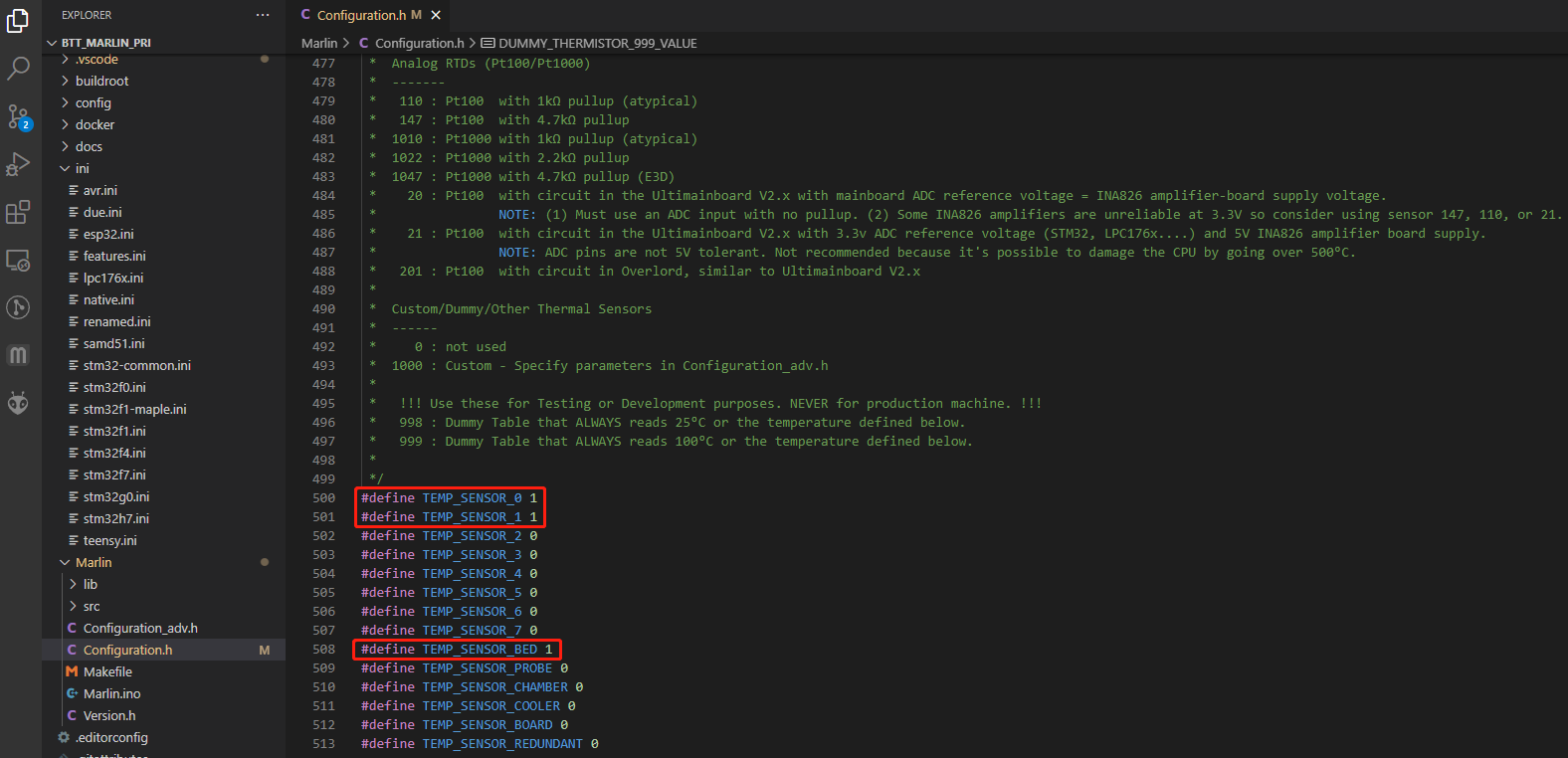
The standard TH ports only support NTC 100K thermistor, In Marlin firmware, "1" represents a 100K NTC with a 4.7K pull-up resistor.
#define TEMP_SENSOR_0 1
#define TEMP_SENSOR_1 1
#define TEMP_SENSOR_BED 1
Max31865
To understand how to wire your sensor, look at the pin diagram and use the dip switch settings that correspond to your connection scheme. Apply the following firmware settings based on your connection scheme and dip switch settings.
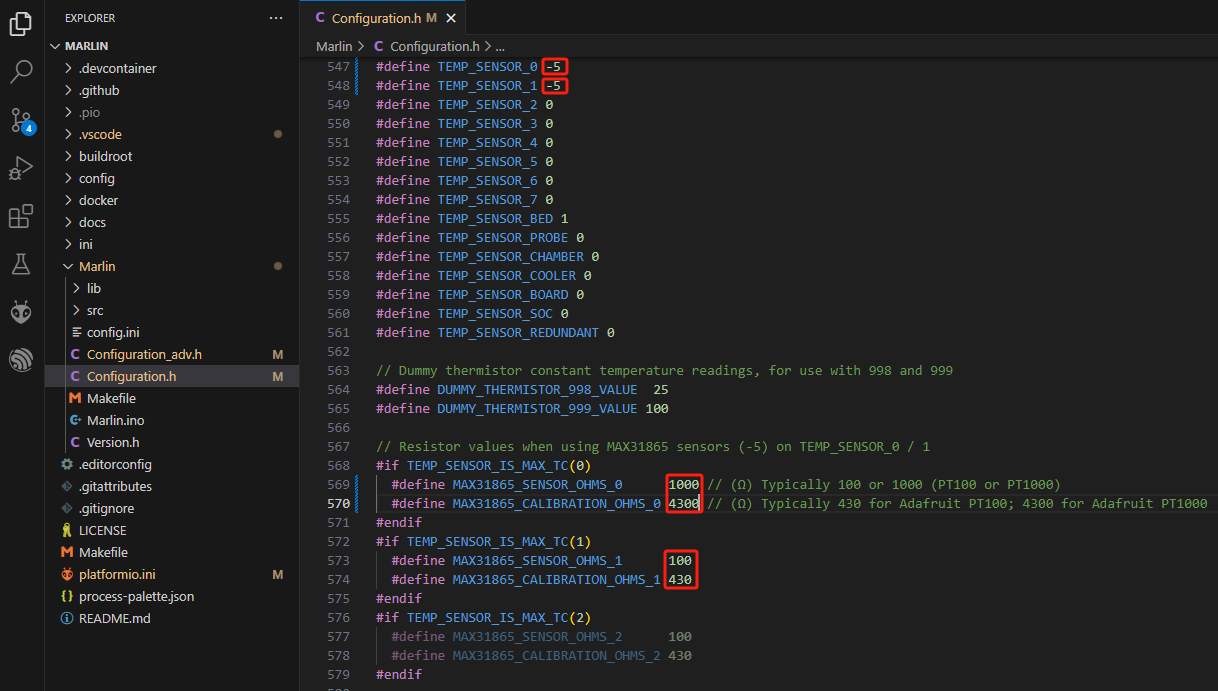
In Marlin (klipper) firmware, "-5" represents max31865, the sensor resistance (rtd_nominal_r) and calibration (rtd_reference_r) resistance of PT100 are 100 and 430, while PT1000 are 1000 and 4300.
#define TEMP_SENSOR_0 -5
#define TEMP_SENSOR_1 -5
BLTouch

//#define Z_MIN_PROBE_USES_Z_MIN_ENDSTOP_PIN // Do not remap the Z_PROBE_PIN to the Z_MIN port.

#define BLTOUCH // Enable BLTouch
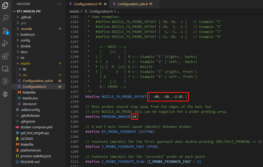
#define NOZZLE_TO_PROBE_OFFSET { -40, -10, -2.85 } // set BLTouch probe offset
#define PROBING_MARGIN 10 // set distance between probe area and print area perimeter
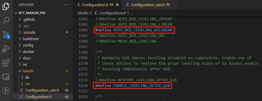
#define AUTO_BED_LEVELING_BILINEAR // set probe pattern
#define RESTORE_LEVELING_AFTER_G28 //apply leveling after G28 homing command
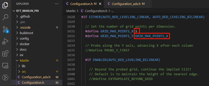
#define GRID_MAX_POINTS_X 5 // set number of probe points for X axis, usually 5 point is sufficient
#define GRID_MAX_POINTS_Y GRID_MAX_POINTS_X // set the number of probe points for Y axis to the same as X axis.
If BLTouch also functions as your Z homing sensor, no wiring change is needed, just set it in the firmware.

#define USE_PROBE_FOR_Z_HOMING // use Z Probe(BLTouch) for Z homing

#define Z_SAFE_HOMING // home Z at the center of print bed to prevent probing outside of the print bed.
Auto Power Off (Relay V1.2)

#define PSU_CONTROL // enable PSU control to turn on and off using M80 and M81
#define PSU_ACTIVE_STATE HIGH // set turn on level, Relay V1.2 is turned on with high level and turned off with low level, so this setting needs to be HIGH.
RGB
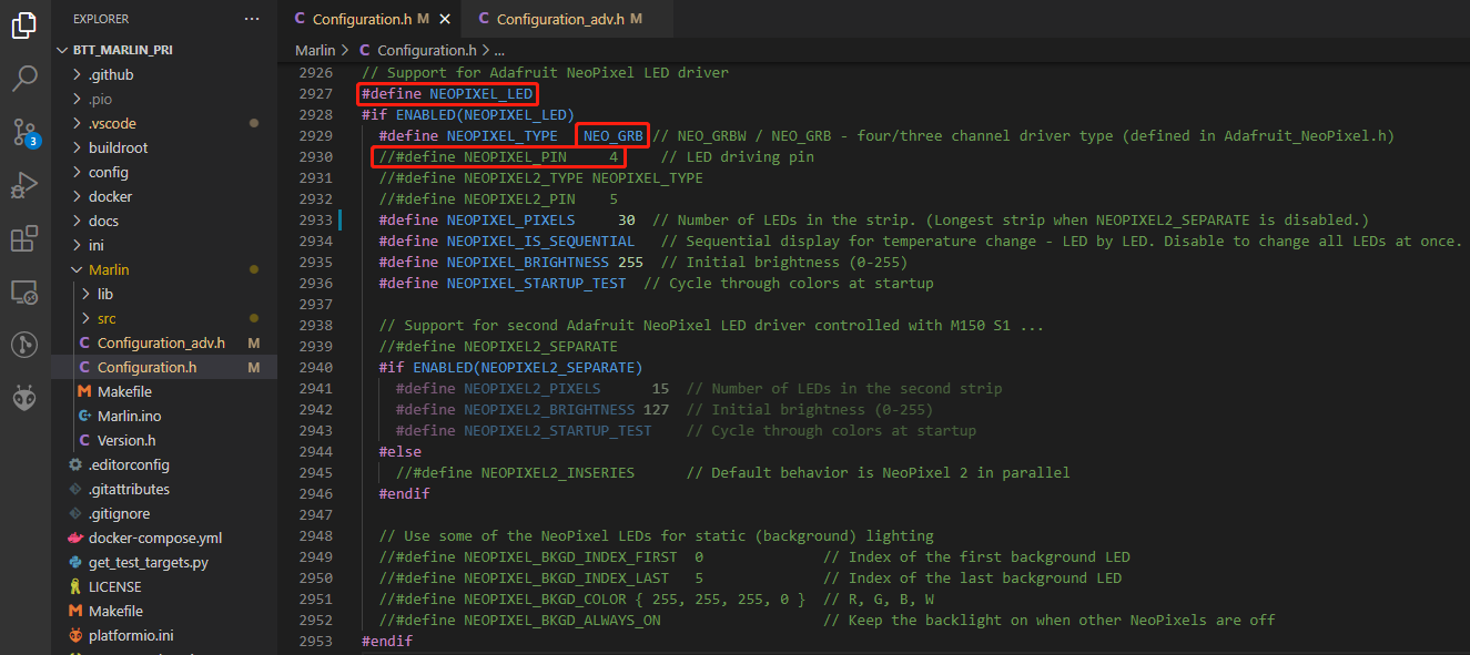
#define NEOPIXEL_LED // enable Neopixel
#define NEOPIXEL_TYPE NEO_GRB // set Neopixel type
//#define NEOPIXEL_PIN 4 // disable PIN setting, use the correct signal pin in the pin file of the motherboard
#define NEOPIXEL_PIXELS 30 // number of LEDs
#define NEOPIXEL_STARTUP_TEST // the light will show red green and blue sequentially to self-test
If you are using displays like LCD2004, 12864, mini12864, etc., you can also control RGB from your display directly.

#define LED_CONTROL_MENU // add LED control to your menu.
Filament Sensor
Standard filament run out sensors are usually comprised of a microswitch which signals the mainboard of filament status with High or Low level signal.

#define FILAMENT_RUNOUT_SENSOR // enable filament run out sensor
#define FIL_RUNOUT_ENABLED_DEFAULT true // true default to filament run out sensor enabled
#define NUM_RUNOUT_SENSORS 1 // number of filament run out sensor
#define FIL_RUNOUT_STATE LOW // voltage level of the filament runout sensor trigger signal. Set according to the actual situation of the module. If the module sends a low level when the filament is abnormal, set it to LOW.
Smart Filament Sensor (SFS V1.0)
The smart filament sensor works by continuously sending signal to the mainboard to communicate filament status.
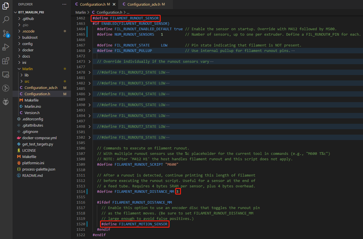
#define FILAMENT_MOTION_SENSOR // set encoder type
#define FILAMENT_RUNOUT_DISTANCE_MM 7 // set sensitivity, SFS V1.0 nominal setting should be 7mm, which means if no signal of filament movement is detected after 7mm of filament travel command, filament error will be triggered.
The settings below also need to be set to instruct the printer to park the nozzle after filament error is detected.


#define NOZZLE_PARK_FEATURE // park nozzle
#define NOZZLE_PARK_POINT { (X_MIN_POS + 10), (Y_MAX_POS - 10), 20 } // set the X, Y and Z offset coordinate of the nozzle

#define ADVANCED_PAUSE_FEATURE // retraction setting of nozzle park movement and filament purge distance after the print is resumed.
Compile Firmware
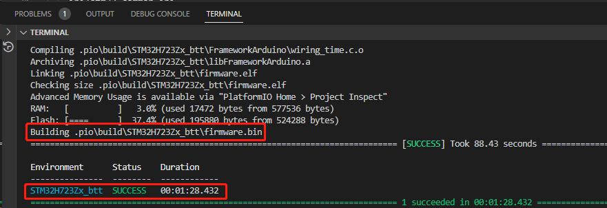
1、Click "√" to compile firmware.

2、Copy the compiled "firmware.bin" to SD card and insert to motherboard to update firmware.
Klipper
Compiling the Firmware
1、Use the following configuration to compile the firmware (if these options are not available, please update the Klipper firmware source code to the latest version):
- [*] Enable extra low-level configuration options
- Micro-controller Architecture (STMicroelectronics STM32) --->
- Processor model (STM32H723) --->
- Bootloader offset (128KiB bootloader (SKR SE BX v2.0)) --->
- Clock Reference (25 MHz crystal) ---> USB Interface
- Communication interface (USB (on PA11/PA12)) ---> CANBUS Interface
- Communication interface (CAN bus (on PD0/PD1)) --->
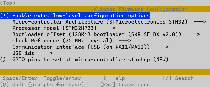
2、Press q to exit, and Yes when asked to save the configuration.
3、Run make to compile firmware, "klipper.bin" file will be generated in home/pi/klipper/out folder when make is finished, download it onto your computer using the SSH application.
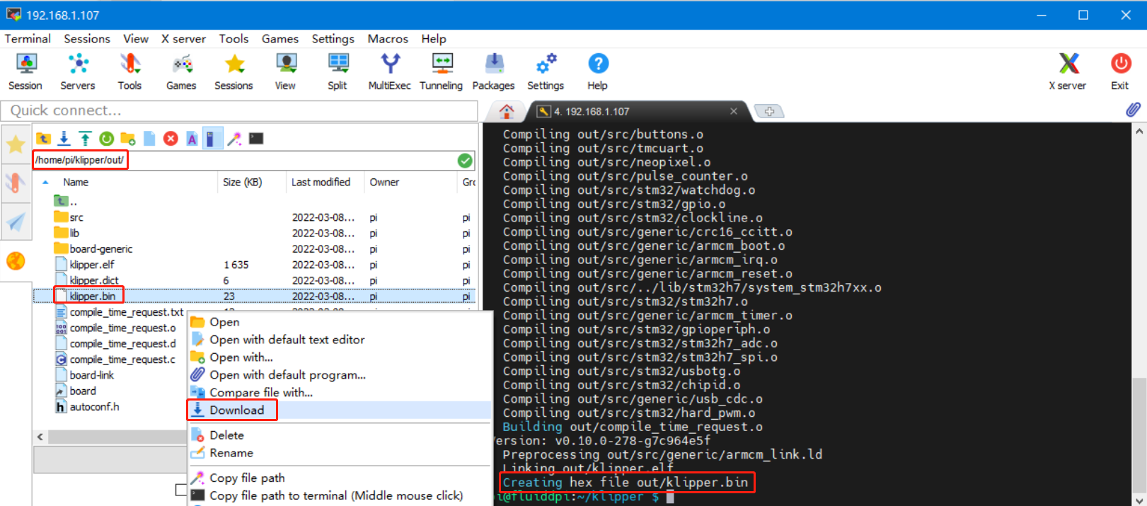
4、Rename klipper.bin to "firmware.bin", copy to SD card to update firmware.
5、Enter:
in command line to check motherboard ID to confirm whether firmware is updated successfully, as shown below.

copy and save this ID, it is needed when modifying klipper config.
Configuring Klipper
1、Enter the Raspberry Pi's IP in a browser to access it. Download the motherboard's reference configuration in the path shown in the image below. If you cannot find this file, update the Klipper firmware source code to the latest version or download from GitHub:
https://github.com/bigtreetech/BIGTREETECH-Kraken
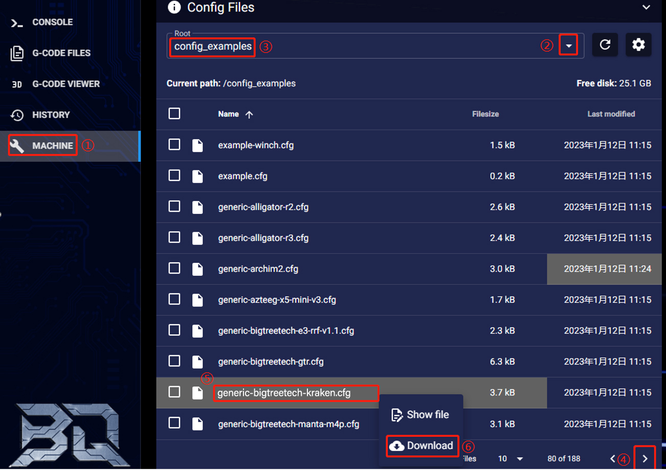
2、Upload the motherboard's configuration file to Configuration Files and include this configuration file in the printer.cfg file.

[include generic-bigtreetech-kraken.cfg]

3、Insert the correct motherboard ID.

4、 Refer to https://www.klipper3d.org/Overview.html for detailed configuration guide according to your machine type.
Firmware Updates
Updating via microSD
- Ensure the microSD card is formatted as FAT32.
- Rename the compiled firmware or the firmware downloaded from GitHub to "firmware.bin" (note: make sure the computer system's extension settings are clear, as some users hide the extension, and "firmware.bin" actually displays as "firmware").
- Copy "firmware.bin" to the root directory of the microSD card.
- Insert the microSD card into the motherboard's slot, power on the motherboard, and the bootloader will automatically update the firmware.
- The status LED will blink during update.
- When it stops and the file is renamed "FIRMWARE.CUR", the update is complete.
Updating Klipper via DFU
1、Run ls /dev/serial/by-id/ to get the board ID. If Klipper is running, it will return a klipper ID.

2、If ls /dev/serial/by-id/ is able to find the MCU's klipper device ID, you can directly input:
to write firmware (Note: Replace/dev/serial/by-id/xxx with the actual ID queried in the previous step)
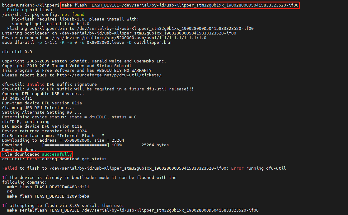
After writing completes, there may be an error message dfu-util: Error during download get_status, just ignore it.
Precautions
1、Forbidden to switch driver voltage when stepper motors are in motion;
2、When switching stepper motor driver voltage, ensure no control signals are being output from the MCU to the driver chips;
3、When driver current exceeds 7A, it is recommended to add a cooling fan for the driver for heat dissipation.