TMC5160T Pro V1.0
Product Profile
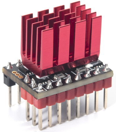
The TMC5160 is a high-power stepper motor driver control chip that uses external power MOSFETs. It can operate at voltages up to 56V, supporting a wider range of stepper motors and offering higher adaptability.
Feature Highlights
- Utilizes external power MOSFETs to support higher voltages and larger currents.
- Generates significantly less heat compared to drivers such as the 2209 and 2130.
- Delivers greater torque to prevent motor-jitter, reducing the likelihood of missing steps.
- Capable of driving 57 stepper motors.
- Adopts a universal driver board design for higher compatibility across various applications.
- Features a heatsink with enhanced fin design for improved cooling.
- Includes expansion interfaces for DIY enhancements.
Specifications
- Dimensions: 20.4mm x 15.3mm x 23.2mm
- Driver Chip: TMC5160-TA
- Input Voltage (VM): 8V-56V (TMC5160T Pro), 8V-24V (TMC5160T)
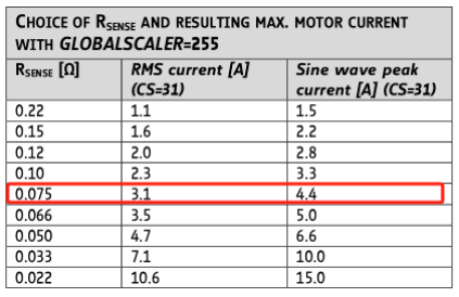
- Maximum Current: RMS 3.1A, Peak 4.4A (base capacity of 3A maximum)
- Maximum Microstepping: 256 steps
- Operating Mode: SPI
Peripheral Interface
Dimensions

Pin Description

| J1 | Functions | J2 | Functions |
|---|---|---|---|
| 1 | (EN) Enable | 1 | (VM) Motor Supply Voltage |
| 2 | (SDI/CFG1) Data | 2 | (GND) Ground |
| 3 | (SCK/CFG2) Clock | 3 | (A2) Phase A |
| 4 | (CSN/CFG3) Chip Select | 4 | (A1) Phase A |
| 5 | (SDO/CFG0) Data | 5 | (B2) Phase B |
| 6 | (CLK) External Clock Input | 6 | (B1) Phase B |
| 7 | (STEP) Pulse Input | 7 | (VIO) Logic Voltage |
| 8 | (DIR) Direction Input | 8 | (GND) Ground |
Interface Introduction
Installation and Interface
The Enable (EN) pin is highlighted in red in the diagram and located inside the marked white box on the driver:

Firmware Settings
Marlin
Note
Marlin firmware version 2.0 or above is required for TMC5160's SPI mode.
Step 1:
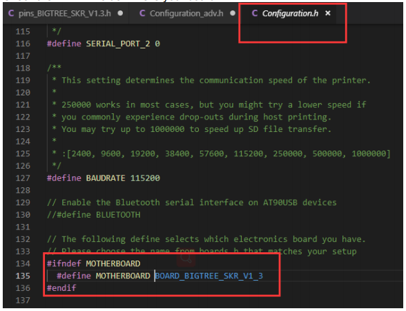
Open Configuration.h in your Marlin 2.0 firmware.
Find #define MOTHERBOARD XXXXXX
Check the XXXXX value. This is your board.
Step 2:
Go to the Marlin/src/pins directory.
Open the pins_xxxxxx.h file that matches your board. (Remember, xxxxxx is your board model from Step 1).
Find these lines:
Change the pin numbers to the ones which you are using.

Step 3:
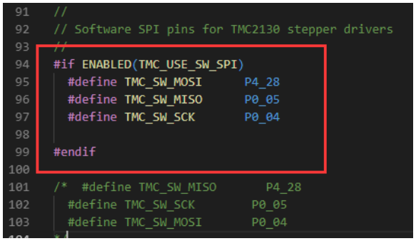
Stay in that same pins_xxxxxx.h file. (The one from Step 2).
Find these lines:
Replace those XXX placeholders with the correct pin numbers for your setup.
Step 4:
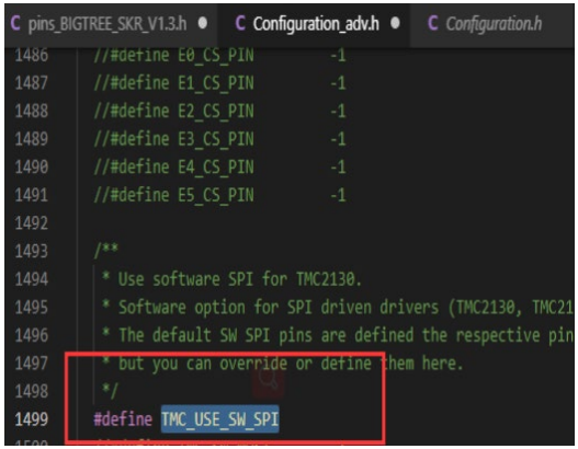
Open the Configuration_adv.h file. Find the line #define TMC_USE_SW_SPI.
Remove the // at the beginning of the line.
Step 5:
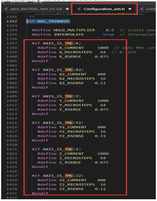
In Configuration_adv.h, find #define X_CURRENT, #define X_MICROSTEPS,
#define X_RSENSE and modify the parameters (modifications are needed for all axes used), setting RSENSE for each axis to 0.075.
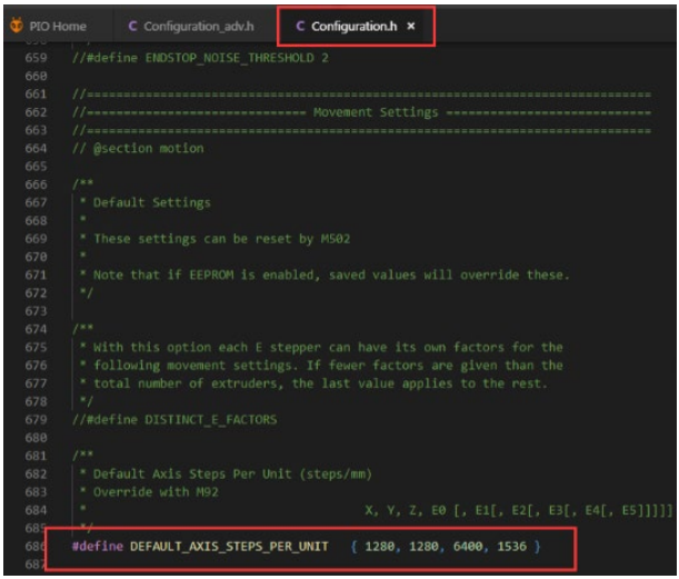
Step 6:
After completing step 5, open Configuration.h and locate #define DEFAULT_AXIS_STEPS_PER_UNIT and modify the parameters to set microstepping, ensuring it corresponds with the microstepping from step 5.
For microstepping calculation, "80,80,400,96" represents 16 microsteps, and if changed to 32 microsteps it becomes "80(32/16), 80(32/16), 400(32/16), 96(32/16)".
Klipper config example
[tmc5160 stepper_x]
cs_pin: PD2
spi_software_sclk_pin: PC6
spi_software_mosi_pin: PC8
spi_software_miso_pin: PC7
run_current: 0.80
sense_resistor: 0.075
interpolate: True
stealthchop_threshold: 0
diag1_pin: ^!PF3
driver_SGT: 0
Change sensing resistor
Warning
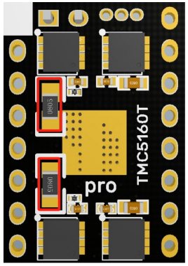
The TMC5160T Pro V1.0 uses a 0.075R current sensing resistor, which sets the maximum effective RMS current to 3.1A.
If you require higher currents, it is possible to replace the current sensing resistor with a new one. Please note that you will need to source and solder it yourself.
Ensure that the replacement resistor is no less than 0.066R due to the size constraints of the module.
Replacing the resistor is not recommended, but if you decide to go ahead, you'll need to take responsibility for any damage that might happen during the swap.
The location for the replacement resistor is indicated by the red box in the diagram below.
Cautions
Cautions
Disconnect power before installing the driver to avoid damage.
Ensure proper orientation during installation to prevent malfunction.
Avoid hot-plugging the driver module to prevent damage.