TMC5160
Product Profile
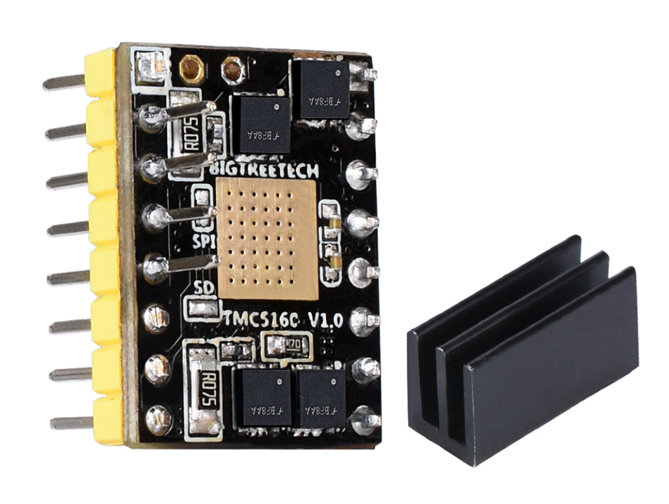
TMC5160 is a high-power stepper motor driving control chip, which has externally expanded power MOS tube, the maximum current can reach 20A, low heat when working.
Supporting TRINAMICS unique stealthChop2 mode eliminates motor noise by reducing resonance and achieves a silent effect.StallGuard2 ™ blocking rotation detection is a safe stop to detect the motor and replaces a mechanical stop switch.It can achieve stepping motor torque control or sensorless back to the origin.
dcStep ™ can let the motor run near its limit load and speed limit, can be achieved in the absence of any step 10 times or more dynamic range.
spreadCycle ™ chopper algorithm has high precision, used for high dynamic motor sports and current wave absolutely clean. Low noise, low resonance and low vibration chopper.
coolStep ™ current control function, optimize the drive performance, balance the speed and motor torque and optimize energy efficiency, drive smoothly and no noise, energy consumption can be reduced by 75%.
TMC5160 is an expansion of the TMC2100, TMC2130 and
TMC5130 series to higher voltages and higher motor currents.
Product Link: BIGTREETECH Official Website
Features Highlights
-
External power MOS tube can support larger current, the maximum current can reach 20A (because the module is limited by area, the current cannot exceed)
-
Super-mute mode
-
Low calorific value
-
can prevent motor shake(5)not easy to lose step
-
can drive 57 stepper motor
Specifications
| Driver chip | TMC5160T V1.0 |
|---|---|
| Product size | 15.3mm*20.4mm |
| Power supply voltage (VM) | 8V-- -40V |
| Maximum current | 4.4A (the sense resistor determines the maximum current) |
| Maximum subdivision | 256 |
| Working mode | SPI mode |
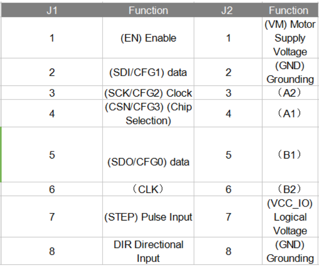
Interface Diagram

Pinout/Function

Hardware Configuration
Driver Current Description
The range of driver current depends on the value of the sense resistor.
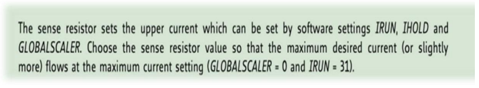
The relationship between the effective value and maximum value of the driver current and the magnitude of the sense-resistor, please see the following picture:
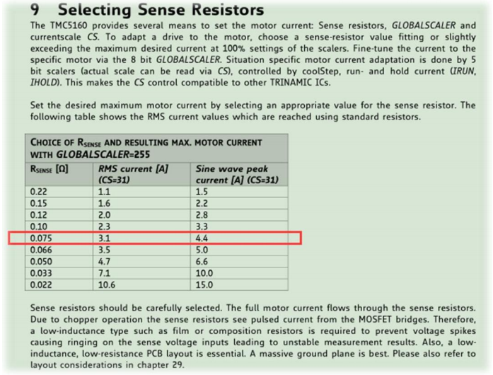
The sense resistors used in the TMC5160-V1.0 is 0.075R, so the effective value of the driver current of this driver is 3.1A, and the maximum current is 4.4A.
If you need to use a larger current, you need to replace the value of the sense resistor yourself (you need to prepare the components and soldering yourself).
Replace the resistor not less than 0.05R (subject to module size limit).
Note: It is not recommended to replace the resistor. If it must be replaced,the driver will be damaged during the replacement process is at your own risk.

Hardware Installation
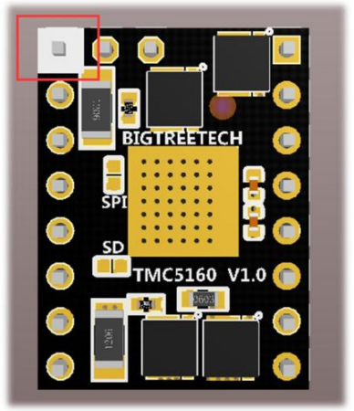
The pins with white block diagram on the driver are enabled (EN) pins as shown in the red box below.
Software Configuration
Klipper Config Example
[tmc5160 stepper_x]
cs_pin: PD2
spi_software_sclk_pin: PC6
spi_software_mosi_pin: PC8
spi_software_miso_pin: PC7
run_current: 0.80
sense_resistor: 0.075
interpolate: True
stealthchop_threshold: 0
diag1_pin: ^!PF3
driver_SGT: 0
Marlin Config
Marlin version
Currently only firmware of Marlin 2.0 and above supports the SPI mode of TMC5160.
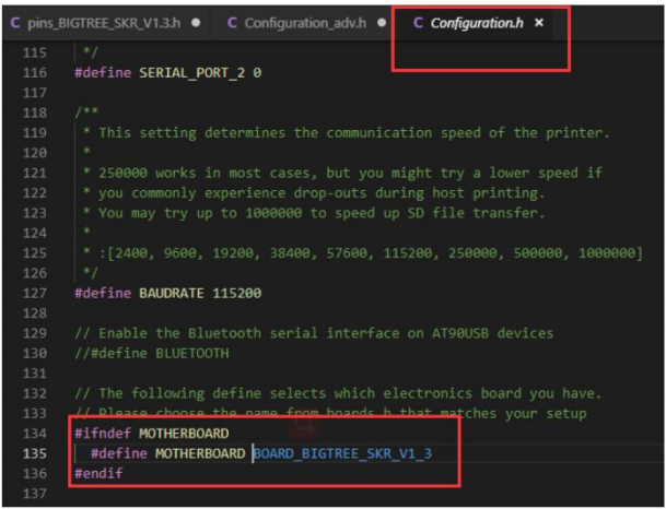
Find and open Configuration.h in Marlin 2.0 firmware File, and then find # define MOTHERBOARD XXXXXX and XXXXX Represents the type of board used. Confirm the motherboard you use.
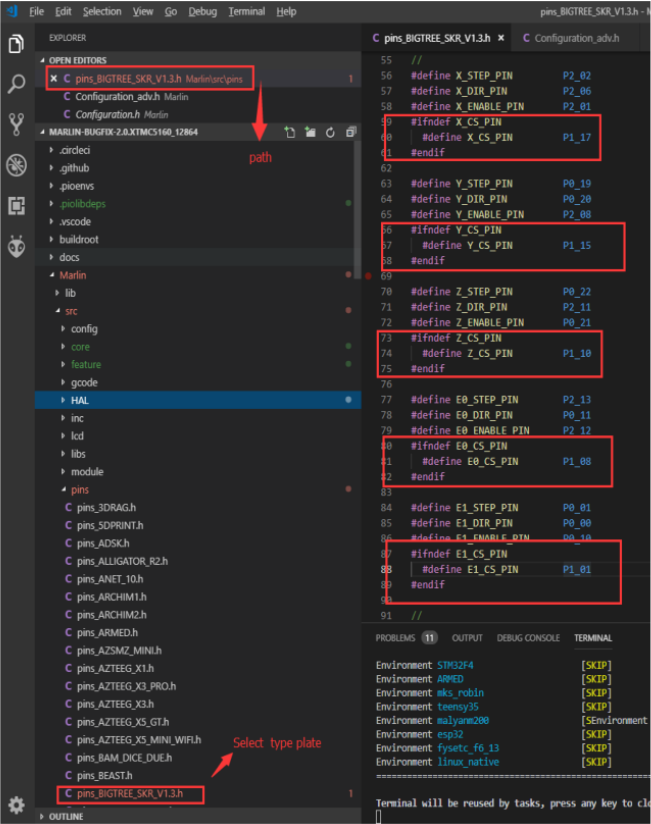
Find the pins_xxxxxx.h file (xxxx represents the model of the board) in the Marlin ./src/pins directory, and then find X_CS_PIN, Y_CS_PIN, Z_CS_PIN, EO_CS_PIN under the file.Finally modify the following pin name to the pin you use.
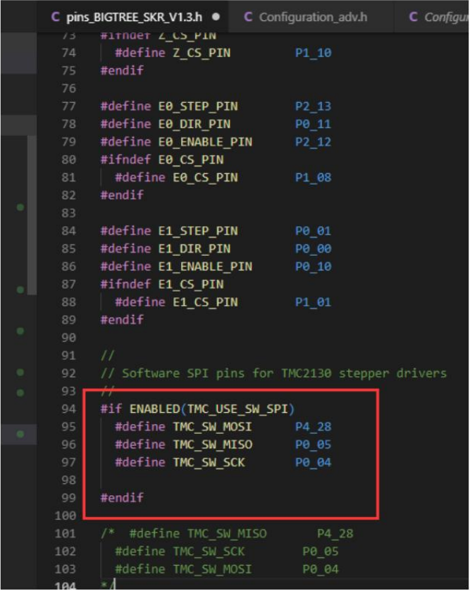
Find #define TMC_SW_MOSI XXX, #define TMC_SW_MISO XXX, #define TMC_SW_SCK XXX under the file in Step 2. Modify XXX to the pin you want to use.
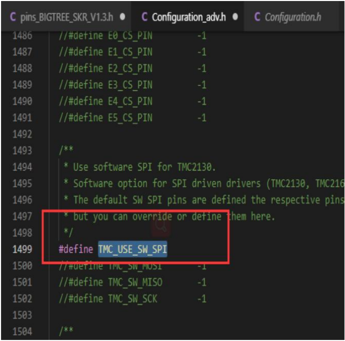
Find and open Configuration_adv.h and then find #define TMC_USE_SW_SPI to remove the comment // to enable.
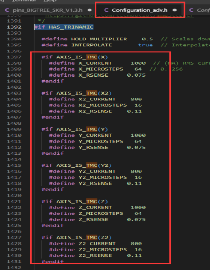
Under the Configuration_adv.h file, find #define X_CURRENT, #define X_MICROSTEPS, #define X_RSENSE. After modification of the parameters (the axes used need to be modified), the RSENE of the axes used should be changed to 0.075
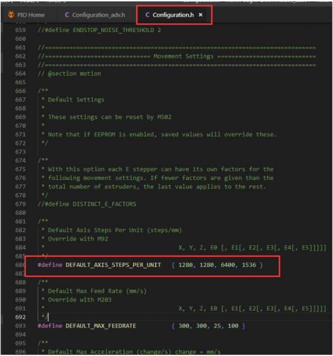
After the modification of Step 5 is completed, find and open Configuration.h and then find #define DEFAULT_AXIS_STEPS_PER_UNIT modifies the following parameters to set the subdivision, which must correspond to the subdivision of step 5.
Subdivision calculation method, 80, 80, 400, 96 represents 16 subdivisions. If modified to 32 subdivisions, it will be 80 * (32/16), 80 * (32/16), 400 * (32/16), 96 * (32/16).
Precautions
Warning
Always disconnect the power supply before installing the driver to prevent the driver from burning.
Be sure to confirm the direction of the driver before installing the driver. Prevent the driver from burning due to reverse connection.
Please do not plug and unplug the driver module when power is on to avoid damage.
When installing the heat sink, please be careful not to contact the heat sink and the pin header to prevent short circuit.
The product is sensitive to static electricity, please handle it carefully when using, it is best to remove the package when using.