CB2
Product Profile
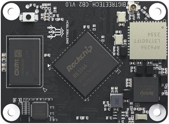
The BIGTREETECH CB2, compatible with the Raspberry Pi CM4 form factor, uses two 100-pin high-speed board-to-board (BTB) connectors for easy and quick connection with external expansion baseboards. It offers an alternative with similar IO capabilities, including Micro HDMI, USB, Gigabit Ethernet, DSI, and CSI outputs. Additionally, it features 2.4G and 5G WiFi, Bluetooth 5.2, the Rockchip RK3566 SoC, 2GB LPDDR4 RAM, and 32GB eMMC storage.
Product Link: BIGTREETECH Official Website
Features Highlights
- CPU: Rockchip RK3566, quad-core Cortex-A55 @1.8GHz
- GPU: Mali-G52 1-Core-2EE
- NPU: 0.8 TOPS NPU
- RAM: 2GB/4GB LPDDR4
- Onboard EMMC
- MIPI DSI display support
- Dual-lane MIPI CSI-2 Camera Interface
- 3x USB 2.0 ports, 1x USB 3.0 port
- PCIe 2.1 1x1 Lane
- Gigabit Ethernet +433Mbps WiFi+BT5.0
- 40-pin GPIO
- BTB socket that is completely identical to the one on the Raspberry Pi CM4
Specifications
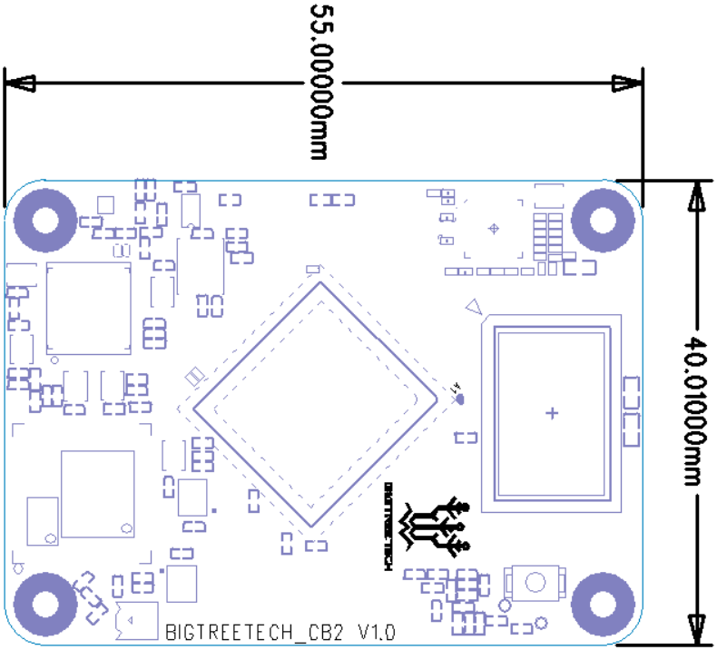
| Dimensions | 40mm x 55mm |
|---|---|
| Mounting Dimensions | 33mm x 48mm |
| Input Voltage | 5V±5%/2A |
| Output Voltage | 3.3V±2%/100mA |
| Output Voltage | 1.8V±2%/100mA |
| WiFi | 2.4G/5G, 802.11 ac/a/b/g/n/ wireless standards |
Dimensions
Peripheral Interface
Pin Description
| PIN | Connector | Signal | Description |
|---|---|---|---|
| 1 | A connector_01 | GND | |
| 2 | A connector_02 | GND | |
| 3 | A connector_03 | GBIT_MDI3_P | |
| 4 | A connector_04 | GBIT_MDI1_P | |
| 5 | A connector_05 | GBIT_MDI3_N | |
| 6 | A connector_06 | GBIT_MDI1_N | |
| 7 | A connector_07 | GND | |
| 8 | A connector_08 | GND | |
| 9 | A connector_09 | GBIT_MDI2_N | |
| 10 | A connector_10 | GBIT_MDI0_N | |
| 11 | A connector_11 | GBIT_MDI2_P | |
| 12 | A connector_12 | GBIT_MDI0_P | |
| 13 | A connector_13 | GND | |
| 14 | A connector_14 | GND | |
| 15 | A connector_15 | 1000M_LED | |
| 16 | A connector_16 | CAMERAB_PDN_L | |
| 17 | A connector_17 | 100M_LED | |
| 18 | A connector_18 | SPDIF_TX_M2 | |
| 19 | A connector_19 | PWM3_IR | |
| 20 | A connector_20 | NC | |
| 21 | A connector_21 | WORKING_LEDEN_H | |
| 22 | A connector_22 | GND | |
| 23 | A connector_23 | GND | |
| 24 | A connector_24 | GPIO0_C3 | |
| 25 | A connector_25 | GPIO4_C2 | |
| 26 | A connector_26 | GPIO4_C5 | |
| 27 | A connector_27 | GPIO4_C3 | |
| 28 | A connector_28 | GPIO0_C0 | |
| 29 | A connector_29 | GPIO0_A0 | |
| 30 | A connector_30 | GPIO3_D7 | |
| 31 | A connector_31 | GPIO0_C1 | |
| 32 | A connector_32 | GND | |
| 33 | A connector_33 | GND | |
| 34 | A connector_34 | NC | |
| 35 | A connector_35 | GPIO0_B3 | |
| 36 | A connector_36 | GPIO0_B4 | |
| 37 | A connector_37 | GPIO0_A6 | |
| 38 | A connector_38 | GPIO3_C3 | |
| 39 | A connector_39 | GPIO4_A2 | |
| 40 | A connector_40 | GPIO3_C2 | |
| 41 | A connector_41 | GPIO3_C4 | |
| 42 | A connector_42 | GND | |
| 43 | A connector_43 | GND | |
| 44 | A connector_44 | GPIO3_C1 | |
| 45 | A connector_45 | GPIO4_A3 | |
| 46 | A connector_46 | GPIO1_A1 | |
| 47 | A connector_47 | GPIO4_C6 | |
| 48 | A connector_48 | GPIO1_A0 | |
| 49 | A connector_49 | GPIO0_C0 | |
| 50 | A connector_50 | GPIO0_C7 | |
| 51 | A connector_51 | GPIO0_D0 | DEBUG UART |
| 52 | A connector_52 | GND | |
| 53 | A connector_53 | GND | |
| 54 | A connector_54 | GPIO3_A1 | |
| 55 | A connector_55 | GPIO0_D1 | DEBUG UART |
| 56 | A connector_56 | GPIO4_B3 | |
| 57 | A connector_57 | SDC0-CLK | SDCARD Clock signal |
| 58 | A connector_58 | GPIO4_B2 | |
| 59 | A connector_59 | GND | |
| 60 | A connector_60 | GND | |
| 61 | A connector_61 | SDC0-D3 | SDCARD Data3 signal |
| 62 | A connector_62 | SDC0-CMD | SDCARD CMD signal |
| 63 | A connector_63 | SDC0-D0 | SDCARD Data0 signal |
| 64 | A connector_64 | NC | |
| 65 | A connector_65 | GND | |
| 66 | A connector_66 | GND | |
| 67 | A connector_67 | SDC0-D1 | SDCARD Data1 signal |
| 68 | A connector_68 | NC | |
| 69 | A connector_69 | SDC0-D2 | SDCARD Data2 signal |
| 70 | A connector_70 | NC | |
| 71 | A connector_71 | GND | |
| 72 | A connector_72 | NC | |
| 73 | A connector_73 | GPIO0_B5 | |
| 74 | A connector_74 | GND | |
| 75 | A connector_75 | GPIO3_D2 | |
| 76 | A connector_76 | GPIO3_D3 | SDCARD detect |
| 77 | A connector_77 | VCC_5V | 5V IN /2A |
| 78 | A connector_78 | NC | |
| 79 | A connector_79 | VCC_5V | 5V IN /2A |
| 80 | A connector_80 | GPIO4_B5 | |
| 81 | A connector_81 | VCC_5V | 5V IN /2A |
| 82 | A connector_82 | GPIO4_B4 | |
| 83 | A connector_83 | VCC_5V | 5V IN /2A |
| 84 | A connector_84 | 3V3 | 3.3v out /200mA |
| 85 | A connector_85 | VCC_5V | 5V IN /2A |
| 86 | A connector_86 | 3V3 | 3.3v out /200mA |
| 87 | A connector_87 | VCC_5V | 5V IN /2A |
| 88 | A connector_88 | 1V8 | 1.8v out /100mA |
| 89 | A connector_89 | GPIO3_B4 | |
| 90 | A connector_90 | 1V8 | 1.8v out /100mA |
| 91 | A connector_91 | NC | |
| 92 | A connector_92 | PWRON | |
| 93 | A connector_93 | RECOVERY | |
| 94 | A connector_94 | NC | |
| 95 | A connector_95 | GPIO4_A1 | |
| 96 | A connector_96 | NC | |
| 97 | A connector_97 | GPIO4_A5 | |
| 98 | A connector_98 | GND |
| 99 | A connector_99 | PMIC_PWRON | |
|---|---|---|---|
| 100 | A connector_100 | AP-RESET | |
| 101 | B connector_1 | USB_OTG0_ID | |
| 102 | B connector_2 | PCIE20_CLKREQn_M 2 | |
| 103 | B connector_3 | USB_OTG0_DM | |
| 104 | B connector_4 | LINEOUTL | |
| 105 | B connector_5 | USB_OTG0_DP | |
| 106 | B connector_6 | LINEOUTR | |
| 107 | B connector_7 | GND | |
| 108 | B connector_8 | GND | |
| 109 | B connector_9 | PCIE20_PERSTn_M2 | |
| 110 | B connector_10 | PCIE20_REFCLKP | |
| 111 | B connector_11 | GPIO4_B0 | |
| 112 | B connector_12 | PCIE20_REFCLKN | |
| 113 | B connector_13 | GND | |
| 114 | B connector_14 | GND | |
| 115 | B connector_15 | MIPI_CSI_RX_D0N | |
| 116 | B connector_16 | PCIE20_RXP | |
| 117 | B connector_17 | MIPI_CSI_RX_D0P | |
| 118 | B connector_18 | PCIE20_RXN | |
| 119 | B connector_19 | GND | |
| 120 | B connector_20 | GND | |
| 121 | B connector_21 | MIPI_CSI_RX_D1N | |
| 122 | B connector_22 | PCIE20_TXP | |
| 123 | B connector_23 | MIPI_CSI_RX_D1P | |
| 124 | B connector_24 | PCIE20_TXN | |
| 125 | B connector_25 | GND | |
| 126 | B connector_26 | GND | |
| 127 | B connector_27 | MIPI_CSI_RX_CLK0N | |
| 128 | B connector_28 | USB3-DM | |
| 129 | B connector_29 | MIPI_CSI_RX_CLK0P | |
| 130 | B connector_30 | USB3-DP | |
| 131 | B connector_31 | GND | |
| 132 | B connector_32 | GND | |
| 133 | B connector_33 | MIPI_CSI_RX_D2N | |
| 134 | B connector_34 | MIC1_IN | |
| 135 | B connector_35 | MIPI_CSI_RX_D2P | |
| 136 | B connector_36 | MIC2_IN | |
| 137 | B connector_37 | GND | |
| 138 | B connector_38 | GND | |
| 139 | B connector_39 | MIPI_CSI_RX_D3N | |
| 140 | B connector_40 | MIPI_CSI_RX_CLK1N | |
| 141 | B connector_41 | MIPI_CSI_RX_D3P | |
| 142 | B connector_42 | MIPI_CSI_RX_CLK1P | |
| 143 | B connector_43 | GPIO4_A7 | |
| 144 | B connector_44 | GND | |
| 145 | B connector_45 | HP_SNS | |
| 146 | B connector_46 | USB2_HOST2_DP | |
| 147 | B connector_47 | HP_DET_L | |
| 148 | B connector_48 | USB2_HOST2_DM | |
| 149 | B connector_49 | SARADC_VIN2 | |
| 150 | B connector_50 | GND | |
| 151 | B connector_51 | HCEC | HDMI CEC |
| 152 | B connector_52 | USB3_HOST1_DP | |
| 153 | B connector_53 | HHPD | HDMI Hotplug |
| 154 | B connector_54 | USB3_HOST1_DM | |
| 155 | B connector_55 | GND | |
| 156 | B connector_56 | GND | |
| 157 | B connector_57 | MIPI_DSI_TX0_D0N | |
| 158 | B connector_58 | USB3_HOST1_SSTXP | |
| 159 | B connector_59 | MIPI_DSI_TX0_D0P | |
| 160 | B connector_60 | USB3_HOST1_SSTXN | |
| 161 | B connector_61 | GND | |
| 162 | B connector_62 | GND | |
| 163 | B connector_63 | MIPI_DSI_TX0_D1N | |
| 164 | B connector_64 | USB3_HOST1_SSRXP | |
| 165 | B connector_65 | MIPI_DSI_TX0_D1P | |
| 166 | B connector_66 | USB3_HOST1_SSRXN | |
| 167 | B connector_67 | GND | |
| 168 | B connector_68 | GND | |
| 169 | B connector_69 | MIPI_DSI_TX0_CLKN | |
| 170 | B connector_70 | HTX2P | HDMI TX2 Positive. |
| 171 | B connector_71 | MIPI_DSI_TX0_CLKP | |
| 172 | B connector_72 | HTX2N | HDMI TX2 Negative. |
| 173 | B connector_73 | GND | |
| 174 | B connector_74 | GND | |
| 175 | B connector_75 | MIPI_DSI_TX1_D0N | |
| 176 | B connector_76 | HTX1P | HDMI TX1 Positive. |
| 177 | B connector_77 | MIPI_DSI_TX1_D0P | |
| 178 | B connector_78 | HTX1N | HDMI TX1 Negative. |
| 179 | B connector_79 | GND | |
| 180 | B connector_80 | GND | |
| 181 | B connector_81 | MIPI_DSI_TX1_D1N | |
| 182 | B connector_82 | HTX0P | HDMI TX0 Positive. |
| 183 | B connector_83 | MIPI_DSI_TX1_D1P | |
| 184 | B connector_84 | HTX0N | HDMI TX0 Negative. |
| 185 | B connector_85 | GND | |
| 186 | B connector_86 | GND | |
| 187 | B connector_87 | MIPI_DSI_TX1_CLKN | |
| 188 | B connector_88 | HTXCP | HDMI CLK Positive. |
| 189 | B connector_89 | MIPI_DSI_TX1_CLKP | |
| 190 | B connector_90 | HTXCN | HDMI CLK Negative. |
| 191 | B connector_91 | GND | |
| 192 | B connector_92 | GND | |
| 193 | B connector_93 | MIPI_DSI_TX1_D2N | |
| 194 | B connector_94 | MIPI_DSI_TX1_D3N | |
| 195 | B connector_95 | MIPI_DSI_TX1_D2P | |
| 196 | B connector_96 | MIPI_DSI_TX1_D3P | |
| 197 | B connector_97 | GND |
| 198 | B connector_97 | GND | |
|---|---|---|---|
| 199 | B connector_99 | HSDA | HDMI I2C |
| 200 | B connector_100 | HSCL | HDMI I2C |
Interface Introduction
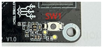
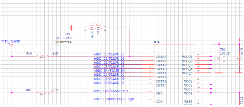
SW1 Button Explanation
Pressing and holding down SW1 will short-circuit the eMMC signal line to GND, prohibiting communication between SoC and eMMC.
40 pin GPIO
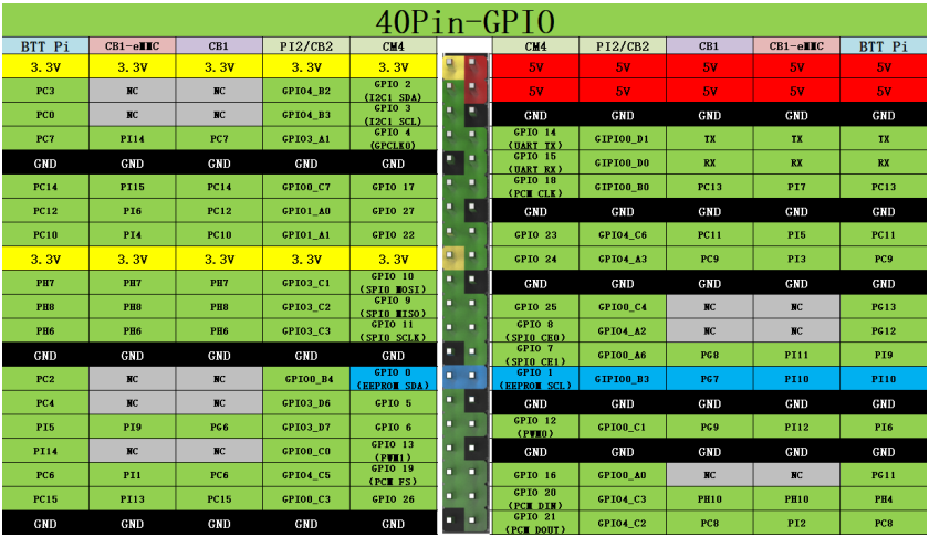
The calculation method for GPIO pins is as follows:
GPIO4_B2 = (‘B’ - ‘A’) * 8 + 2 = 1 * 8 + 2 = gpiochip4/gpio10
GPIO3_D7 = (‘D’ - ‘A’) * 8 + 7 = 3 * 8 + 7 = gpiochip3/gpio31
Flashing the System
Download the System Image
Only use the image provided in bigtreetech/CB2/releases
Write System to MicroSD Card
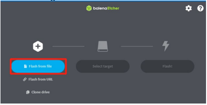
-
Download the balenaEtcher software from balena.io/etcher, install, and run it.
-
Insert the MicroSD card via a card reader.
-
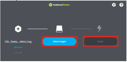
Select your downloaded image.
-
Select the MicroSD card and click "Flash" (WRITE the image will format the MicroSD card. Be careful not to select the wrong storage device, otherwise the data will be formatted).
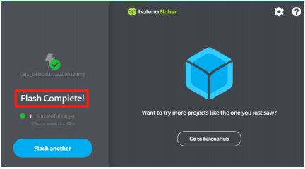
-
Wait for the process to complete.
Writing System onto eMMC
Using RKDevTool (Windows) to Write the eMMC
Download and unzip RKDevTool.zip from the GitHub repo bigtreetech/CB2 to your computer. DO NOT insert a MicroSD card.
-
Turn the DIP switch 4 (USBOTG) and 3 (RPIBOOT) to the ON position to enter BOOT mode.
-
Then, connect the Type-C cable to the computer.
-
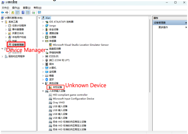
Install the driver:
-
In “Device Manager”, if you see “Unknown Device”, it indicates that the computer is missing drivers.
-
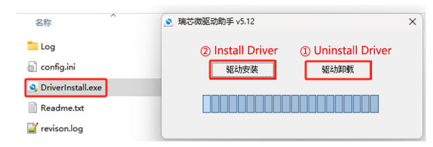
Open the DriverAssistant tool in the downloaded RKDevTool folder, click “①Uninstall Driver”, then click “② Install Driver” to ensure that the latest version of the driver is installed.
-
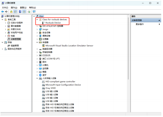
After the installation is complete, hold down the “Recovery” button, replug the Type-C cable. "Device Manager" should now recognize a “Rockusb Device”, indicating that the driver installation is successful.
-
-
Open the “RKDevTool” software:

Note
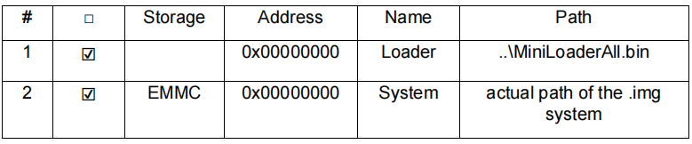
The parameters in the software are set by default as shown in the image. Normally, you only need to set the “4 actual path of the .img system”. If the parameters in your software do not match those in the image, manually adjust them to match.
-
Find the path where the downloaded RKDevTool is located.
-
Open the RKDevTool tool.
-
The software will recognize a “LOADER” or “MASKROOM” device.
-
Select the system to be written (the OS image must be unzipped as a .img file beforehand; RKDevTool does not support directly writing compressed .xz files).
-
Check “Write by Address”.
-
Click “Run” to start writting the system.
-
“Download image OK” indicates that the system has been successfully burned.
-
-
After writing is complete, toggle the USB OTG switch to the OFF position to boot normally. Note: Files on the eMMC cannot be accessed by the computer like those on a MicroSD card, so you cannot modify the system.cfg configuration file to set up the WiFi network. Instead, use an Ethernet cable or USB-to-UART connection to configure the terminal.
Writing System onto eMMC Using a MicroSD Card
-
First, write the system onto the MicroSD card. Then, insert the MicroSD card into the motherboard's card slot and wait for the system to boot.
-
Connect to the system terminal via Ethernet cable, WiFi, or USB to UART, and log in to the system.
CB2 image minimal username and password
CB2 image with Klipper username and password
root account
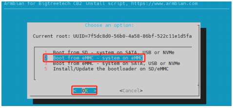
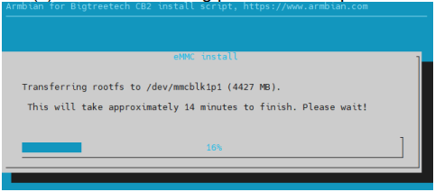
Execute the command sudo nand-sata-install. In the interface that pops up, select 2 Boot From eMMC - system on eMMC and then select OK
-
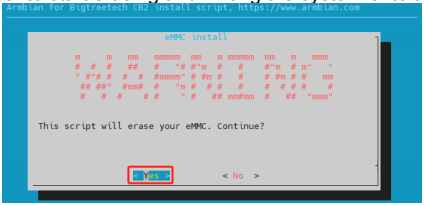
Select "Yes" to start erasing and writing the system onto the eMMC.
-
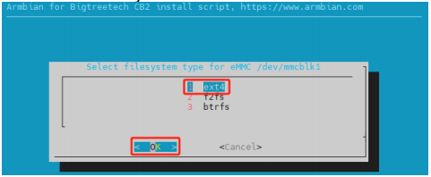
Choose the filesystem "1 ext4" and then select "OK".
-
Wait for the writing process to complete.
-
Upon completion, you will be prompted whether to power off. Select “Power off” to shut down the system.
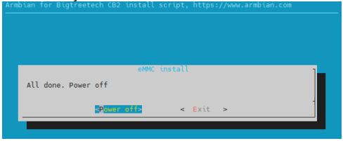
-
After the system has powered down, disconnect the power supply, remove the MicroSD card, and then reconnect power. The system should now boot from the eMMC.
Erasing eMMC
When using a MicroSD card as the system card instead, it's best to erase the data on the eMMC to prevent the motherboard from booting from it by mistake.
Using RKDevTool (Windows) to Erase eMMC
-
Refer to the steps in Using RKDevTool to Write the eMMC (Windows) to connect the motherboard to the computer.
-
Open the
RKDevTool.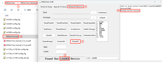
-
Find the path where the downloaded RKDevTool is located.
-
Open the RKDevTool.
-
The software will recognize a
LOADERdevice. If it recognizesMASKROOM, it indicates there is no data in the eMMC, hence no erase operation is necessary. -
Click
Advanced Function. -
Click
EraseAllto begin erasing data from the eMMC. -
Erasing sectors successindicates the erasure is complete.
-
Erasing eMMC After Booting from MicroSD Card
-
Refer to the steps in Writing System onto eMMC Using a MicroSD Card and log into the system terminal.
-
Run the command sudo mkfs /dev/mmcblk1 and then enter
yto confirm.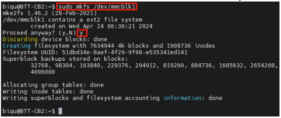
System Configuration
Using Ethernet
Ethernet is plug-and-play and requires no additional setup.
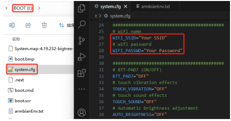
Setting Up WiFi
After the system image has been written, the MicroSD card will have a FAT32 partition recognized by the computer. In this partition, there is a system.cfg file. Open it and replace Your SSID with your actual WiFi name and Your Password with the actual password.
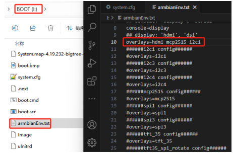
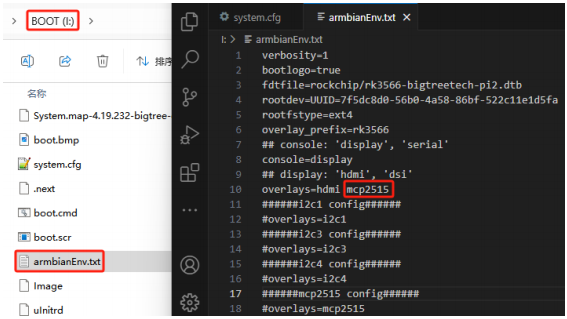
Configuring Overlays
Open the armbianEnv.txt file in the BOOT partition and set the values for overlays. The configurati on file supports only one line of overlays at a time; if multiple overlays are enabled, only the last line will take effect. If you need multiple overlays, place the contents of multiple configurations on the same line separated by a space. For example, if you need to use a DSI screen, MCP2515 SPI to CAN module, and I2C1 simultaneously
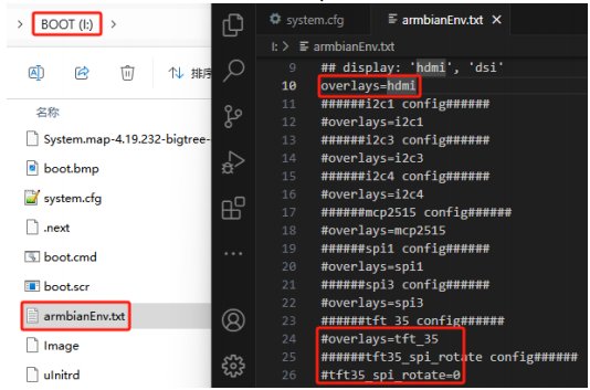
Configuring the Display
-
Open the "armbianEnv.txt" file in the BOOT partition.
-
The default overlay is set to "hdmi," meaning the system uses an HDMI screen by default. This can be changed to match the actual screen being used, such as:
-
hdmi: HDMI screen -
dsi: DSI screen -
tft_35: SPI Screen
For tft_35, there is also a tft35_spi_rotate parameter for system-level screen rotation, with default "0" meaning no rotation, other options include 90, 180, 270.
Note
Only one screen type can be used at a time.
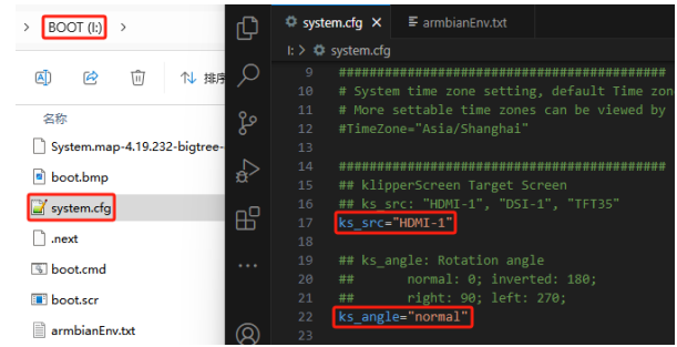
- To configure KlipperScreen, open the
system.cfgfile in the BOOT partition. Set the screen type with the parameterks_src, and the rotation angle withks_angle.
Using SPI to CAN
Open the armbianEnv.txt file in the BOOT partition and add mcp2515 to the overlays configuration.
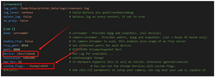
Using CSI Camera and Crowsnest Configuration
For both RPi v1.3 ov5647 and RPi v2 imx219 cameras, no specific configuration in "armbianEnv.txt" is required as they are plug-and-play. "crowsnest.conf" file configuration is as follows:
device: /dev/video0
# The CSI camera node is fixed as video0

custom_flags: --format=UYVY
# The current system's CSI camera does not support the default YUYV, so it needs to be set to the supported UYVY format.
Using Bluetooth
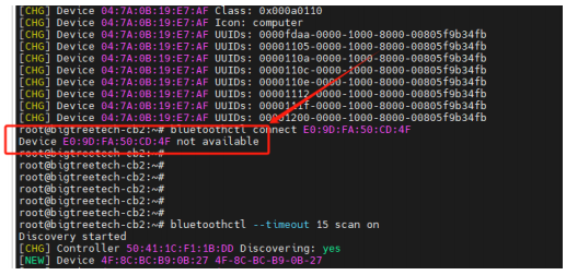
-
To scan for Bluetooth devices, enter the following command, and a list of Bluetooth devices will appear as shown below:
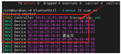
-
Find your Bluetooth device, for example, if your device name is "HONOR xSport PRO", locate the corresponding Bluetooth MAC ID as shown below.

-
To connect to a Bluetooth device, enter the following command, connection success is shown as below
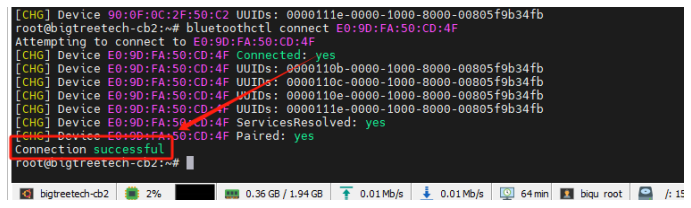
-
If there's an issue while connecting, as shown below, please restart the Bluetooth device and repeat steps 1 and 2 to connect.
-
If there's an issue while connecting, as shown below, please enter the following commands and then repeat steps 1 and 2:
bluetoothctl remove E0:9D:FA:50:CD:4F # Your Bluetooth device's corresponding MAC ID
rfkill block bluetooth
sleep 3s
rfkill unblock bluetooth
pulseaudio -k
pulseaudio –start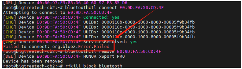
-
-
If you exit voice playback during the use of Bluetooth and cannot reuse it, manually delete the corresponding playback process. Use the ps command to view the process number, then use
kill -9 <process_number>to delete the corresponding playback process.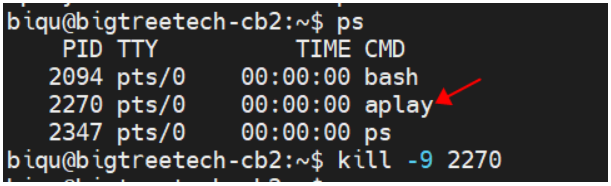
Setting up 3.5mm Headphones Port
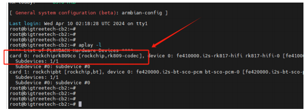
-
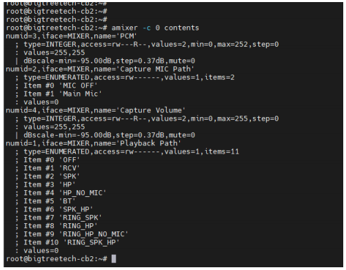
Enter the command:
Check for the corresponding sound card, as shown in the image (the sound card for the headphone port shown in the image corresponds to card 0).
-
Enter the command:
Check the settings for playback and recording channels, as shown in the image.
-
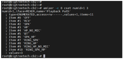
Enter the command:
Set the playback channel, as shown in the image.
-
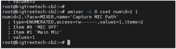
Enter the command:
Set the recording channel, as shown in the image.
-
Enter the following command to play audio, with the audio file directory xxx and the audio file name xxxxx.wav:
- Enter the following command to record (where 10 represents recording for 10 seconds), storing the recording in directory
/path/to/, file namefile.wav.
- Enter the following command to play the recording:
SSH Connect to Device
SSH Application
Install the ssh application Mobaxterm: https://mobaxterm.mobatek.net/download-home-edition.html
-
After powering on, wait for the system to boot, which typically takes about 1 to 2 minutes.
-
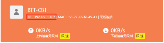
Once the device is connected to WiFi or an Ethernet cable is plugged in, it will automatically be assigned an IP address.
-
Access the router management interface to find the device's IP (it should be BTT-CB2 here).
-
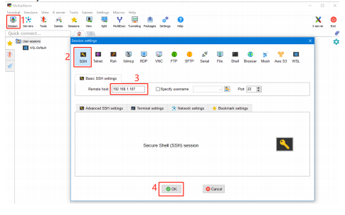
Open Mobaxterm and click "Session", and click "SSH", inset the device IP into Remote host and click "OK" (Note: your computer and the device needs to be in the same network).
-
Login as:
biqupassword:biqu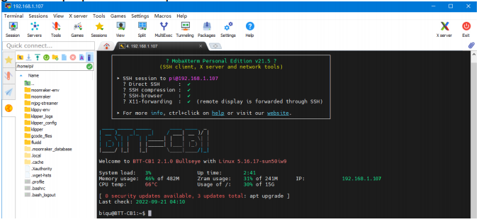
Precautions
Boot from eMMC
When booting from eMMC, do not insert a MicroSD card. When booting from a MicroSD card, it is necessary to erase the data in the eMMC.
-
About 10 seconds after powering on, the system enters the kernel phase. At this time, the blue light stays on, and the green light flashes continuously, indicating that the system is running normally.
-
user account
-
The PCIe M.2 interface does not support hot-plugging; the solid-state drive must be connected in advance for the device to be recognized.