EBB36 GEN2 V1.0
- Product Link: Buy Here
Revision Log
| Version | Date | Update Notes |
|---|---|---|
| v1.00 | October 17th, 2025 | Initial Release |
| v1.1 | October 24th, 2025 | Corrected an error with heater output power rating |
Introduction
A generational leap in toolboard design.
Protection everywhere to reduce the risk of damage, combined with signal-boosting hardware to deliver rock-solid CAN and USB performance.
Switch between CAN and USB with a simple jumper.
Enjoy the industry’s most advanced and reliable toolboard.
Key Features
-
Circuit protection on almost every input and output to prevent damage through unintentional connection mistakes.
-
Switch between CAN and USB connectivity using a single jumper, and the passthrough port automatically adjusts to the new setting.
-
Signal boosters to ensure rock solid USB connectivity.
-
Tested up to 75°C chamber temperatures for long-term performance (a fan is recommended when operating above 60°C chamber temperature).
-
3-pin tacho fan for hotend fan failure detection.
-
Voltage selection (5V/24V) available for all fans.
-
I²C port for connection to environmental or Eddy sensors.
-
Thermistor dedicated to motor driver temperature sensing.
-
Three PWM-controllable fan outputs with short-circuit and thermal protection.
-
Relocated reset and boot buttons for convenient access.
-
Main control chip: ARM Cortex-M0+ STM32G0B1CBT6, 64MHz.
-
Grounded mounting holes for ESD dissipation.
Technical Specifications
| Product Name | BIGTREETECH EBB 36 GEN2 V1.0 |
|---|---|
| Main Control Chip | ARM Cortex-M0+ STM32G0B1CBT6, 64MHz |
| Mainboard Input Voltage | DCIN=DC24V-DC28V |
| Logic Voltage | DC3.3V |
| Heater Port Power | 120 W (24 V / 5 A) |
| Hotend Thermistor Compatibility | PT1000 or NTC |
| Fan Interfaces | Two 2-pin PWM fans (FAN0, FAN1) One 3-pin fan (FAN2) with tachometer feedback. |
| Fan Interface Rated Current | Total: 1 A, Peak Current: 1.5 A Built-in protection against over-current and over-temperature. |
| Maximum 5 V Output Current (Mainboard) | Peak: 1.5 A |
| Expansion Interfaces | Probes (Multiplexed Microprobe, BLTouch, 24 V Probe port), RGB, TH, motors, USB/CAN expansion ports, and others. |
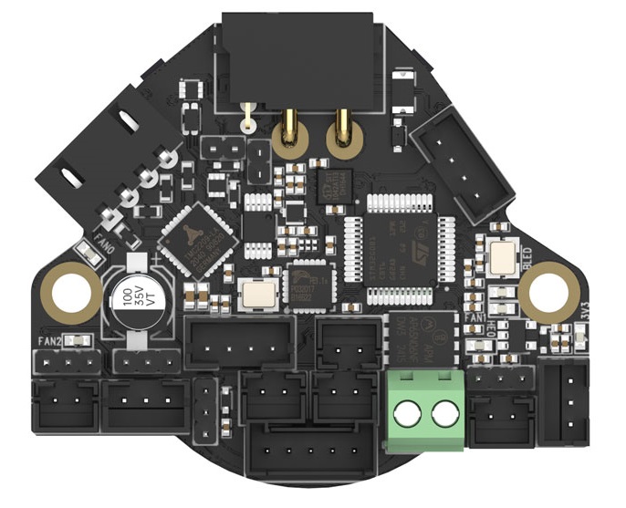
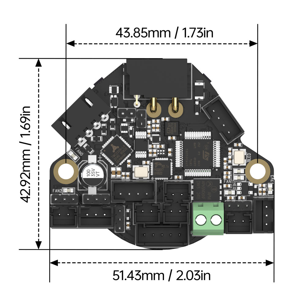
Product Dimensions
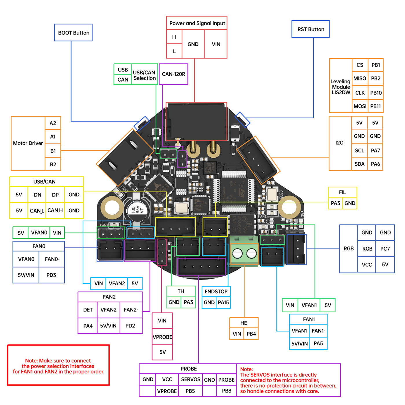
Peripheral Interfaces
EBB36 GEN2 Interface Diagram
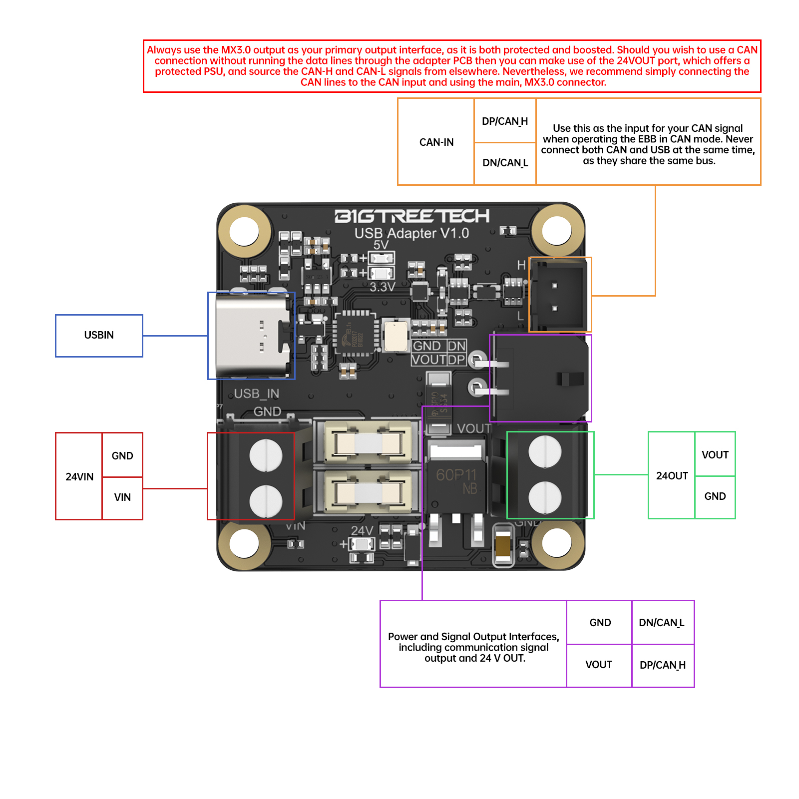
EBB USB Adapter Interface Diagram
Interface Descriptions
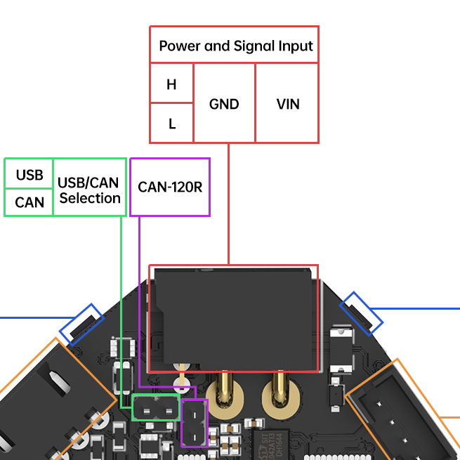
Power Supply Interface
-
Important Notes on the EBB USB Adapter
To fit as much functionality as possible onto the toolboard, some essential protection components have been moved onto the adapter board. Therefore, the power supply starts at the adapter board and this board should not be bypassed during installation.
-
Power Connection Method
To connect the power supply, simply use the provided wires to connect the adapter board to a 24V power source. Take careful note of the polarity of the connection as specified by the pin diagram and silkscreen on the PCB. The adapter board features an MX output connector which carries power and communication signals. For users who may want to use an older harness type with discrete wiring for power and signal, we have also made an output power screw terminal available.
Note that this should only be used for CAN connections since USB connections require the use of the provided cable due to shielding.
The power supply interface uses an XT30 interface, rated for 24V power supply. If you wish to run the cable through a gland then you may need to remove the MX connector which can be done using a tool such as this one: Molex Microfit 3.0 Extractor
When re-inserting the wires into the MX connector, please ensure that you insert them in exactly the same order that they were removed.
-
Multi-Faceted Protection
The power supply features multi-faceted protection. It is protected against reverse polarity in two stages, a first-stage MOSFET circuit on the adapter board and a second-stage, emergency diode circuit on the toolboard. It is protected against short-circuit conditions via a fuse circuit which will open at 5A. Note that it is fuse protected on both the positive and ground voltage rails which ensures that even the ground rail is protected under reverse voltage conditions when the USB port is connected. Tough as nails.
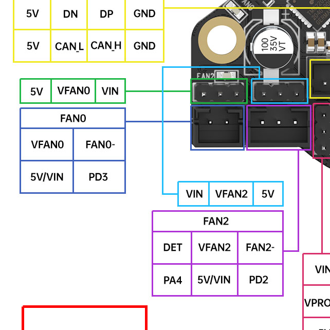
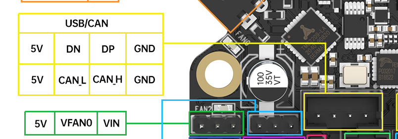
Fan Interface
-
FAN0, FAN2 Output
-
FAN1 Output
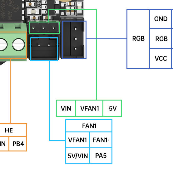
There are three fan interfaces: FAN0, FAN1 and FAN2; FAN0 and FAN1 are 2-wire interfaces while FAN2 is a 3-wire interface. The three fan interfaces are set to output voltages of 5V or 24V by jumpers.
The FAN2 interface takes advantage of the fact that hotend fans are usually driven at 100% PWM duty cycle to implement tacho feedback via a 3-wire interface. This allows your firmware to detect if the fan is not spinning when it should be spinning which can prove to be critical in the case of a hotend fan.
Note: FAN0 and FAN2 have voltage selection jumpers that are adjacent to each other however their voltage selection pin ordering is reversed. This was an intentional routing decision made to ensure that the current delivery track was wide for both fans. Please ensure that you select the correct voltage for your fan; otherwise, you may burn your fan out which BIGTREETECH cannot be held responsible for.
Multi-Faceted Protection
The fan outputs feature multi-faceted, automotive-grade protection. First, they feature flyback protection to ensure that they can drive inductive loads without becoming damaged. Second, they feature an automotive-grade MOSFET which has integrated short-circuit, over-voltage, thermal, over-current, and ESD protection.
Thermistor Interface
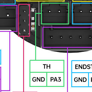
The external thermistor interface is compatible with PT1000 and NTC sensors. It features a 2k2 pull up resistor as well as ample protection circuitry.
Multi-Faceted Protection The circuit protection is multi-faceted. First, the thermistor input "high-side" is protected against a direct short circuit to 24V using a high impedance input circuit that diverts excess current back to the 3.3V rail. Second, the "low-side" is also protected against direct short-circuit to 24V using a resettable fuse that trips under short circuit conditions. The effect of these measures is such that even fault conditions at the hotend, where thermistor and heater wires are often run close to each other, are unlikely to cause damage to your toolboard.
RGB Interface
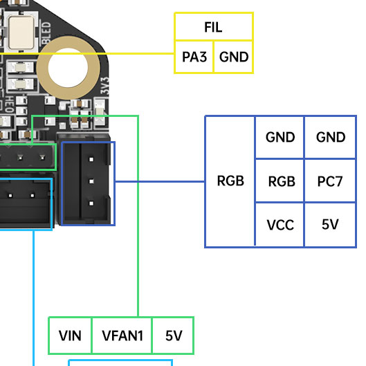
A three-pin RGB interface is provided. This interface is buffered via a level shifter such that the output drive signal operates at the full 5V swing.
Multi-Faceted Protection This interface features multi-faceted protection. It is ESD-protected using a high-impedance between the buffer chip and the output, and it is momentary-short-circuit protected using a Schottky diode that directs excess current back to the 5V rail.
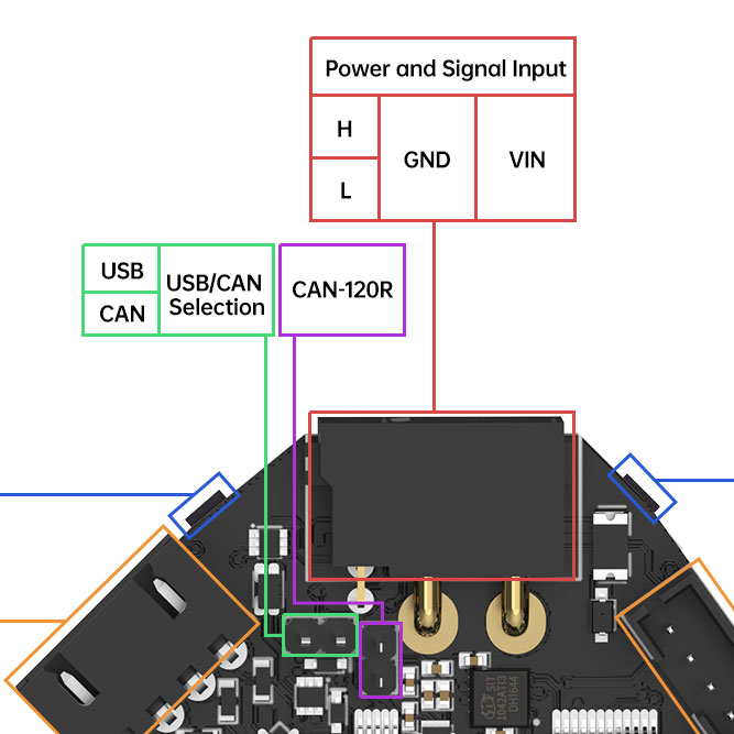
Communication Interface
The toolboard supports both USB and CANBus communication. The desired interface can be selected using a simple jumper connection according to the simple rules below:
-
USB Mode → No jumper
-
CAN Mode → Install jumper
When an interface is selected, both the input port and the passthrough port will adapt to support the selected interface. This means that you will have available either a CAN or USB expansion port on the toolboard.
If you select CANBus then please note that there is an optional 120R termination resistor on the toolboard which can be used if this is the last device in the CANBus physical network. Activate the resistor by inserting the appropriate jumper shown in the image below.
Both communication interfaces require the use of the adapter board. Never connect both the CAN interface and the USB interface at the same time otherwise you may cause damage to your host device. If using the USB interface, simply connect to the USB-C port. If using the CAN interface then make use of the JST-XH port. In both cases, 24V will also be required.
Multi-Faceted Protection The communication bus features multi-faceted protection. First, both the USB and CANBus interfaces are protected against ESD strikes. Second, both the USB and CANBus interfaces are protected against direct short circuits to 24V on their communication pins. We do not recommend creating this fault condition intentionally as the protection circuit used for USB is not designed to sustain rapid short-circuit switching.
For USB communication, the board requires the use of an adapter board. As shown below, the adapter board connects to the host computer via a Type-C interface, and links to the EBB36 GEN2 V1.0 board using the MX3.0 to XT30 cable.
Note: The Type-C interface on the adapter board cannot supply power to the EBB36 GEN2 V1.0. A separate 24 V power supply must be connected to the board.
The passthrough port can be seen in the image below.
Probe Interface
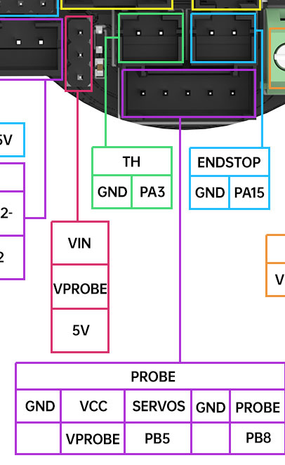
The probe interface increases feature density on the toolboard by multiplexing support for the following probe types into a single port:
- BIQU MicroProbe
- BLTouch
- 24V inductive probe
You can configure the operating voltage using a hardware jumper. The probe can be set to operate at the input voltage to the toolboard or at 5V.
Note: Ensure that you select the correct voltage before connecting your probe.
The probe output is pulled up to the voltage rail that is selected by the jumper.
Multi-Faceted Protection The probe port features multi-faceted protection. First, the probe pin is protected against ESD. Second, it is protected against over voltage via an opto-coupler.
Note: The servo pin has no protection at all by design. This pin was left as the only pin with a direct connection to the MCU as a provision for implementers should they need such. Therefore, special care should be taken when interfacing with this pin to ensure correct connections.
Heater Interface
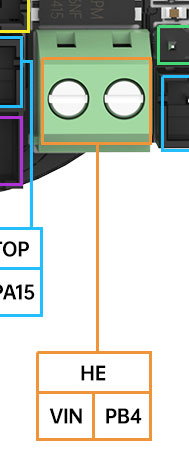
The heater output uses drop-down, pressure plate type screw terminals. Please do not use wires with soldered ends for this connection as it could cause a poor connection if the solder creeps with time.
Note: The voltage of the heater interface is the same as the input voltage. If the input is connected to > 24V, then you need to see whether the heater element supports > 24V input.
The heater output features flyback protection while short circuit protection is provided via the fuses on the adapter board.
Motor Interface
The motor interface uses a TMC2209 motor driver and features a right-angle JST-XH connector with the coil pinout as shown below.
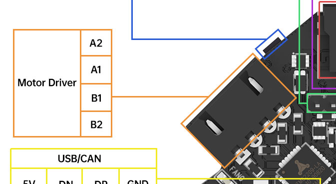
The motor interface is protected against flyback and ESD via a series of TVS diodes on each coil output.
An NTC thermistor is placed directly beneath the motor driver to provide accurate thermal measurements of the motor driver. It can be configured using the guidelines in the firmware section.
Switch Interface
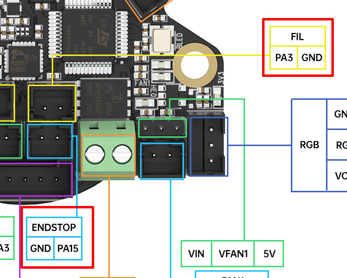
Two switch interfaces are provided for use according to your specific implementation needs. They are labeled as Filament and Endstop.
Both inputs are pulled up to 3.3V and feature multi-faceted protection. First, they are protected against ESD strikes, and second, they are protected against momentary short-circuits using a Zener diode and a current-limiting resistor.
Motor Grounding and Mounting Hole Instructions
The toolboard features connections to the ground rail via 100k resistors on each mounting hole. These are essential to ensure that any static charge that builds up in the motor is dissipated before it can develop into an ESD strike which may cause an MCU reset and affect printing.
To take full advantage of this feature, ensure that you use conductive mounting between the toolboard and the motor chassis. If you do not have a conductive mounting then consider running a cable between the toolboard mounting holes and the motor chassis using a wire with crimped ring terminals on either end.
I²C Interface
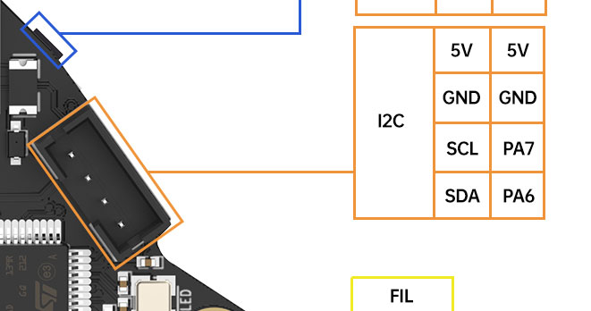
The I²C interface provides a means to connect devices such as environmental sensors and Eddy current probes. The port features integrated pull-up resistors to 3.3V.
Multi-Faceted Protection The I²C port features multi-faceted protection. It is protected against momentary short-circuits as well as ESD strikes using a high impedance resistor Schottky diode network.
Klipper
menuconfig
[*] Enable extra low-level configuration options
Micro-controller Architecture (STMicroelectronics STM32) --->
Processor model (STM32G0B1) --->
If you do not use katapult
Bootloader offset (No bootloader) --->
If katapult is used
Bootloader offset (8KiBbootloader) --->
Clock Reference (8 MHz crystal) --->
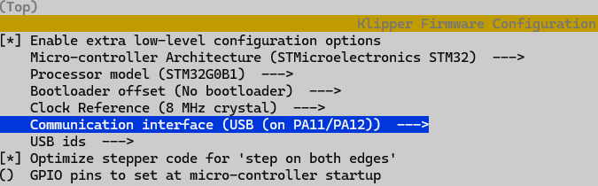
If USB communication is used
Communication interface (USB (on PA11/PA12)) --->
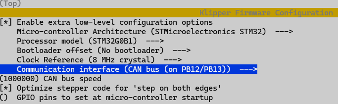
If CAN bus communication is used
Communication interface (CAN bus (on PB12/PB13)) --->
USB ids --->
[*] Optimize stepper code for 'step on both edges'
() GPIO pins to set at micro-controller startup
USB
CAN bus
Notes
- When powered at 24 V, each of the three fan interfaces can supply up to 1 A individually. When powered at 5 V, the total combined current of all three fan interfaces must not exceed 1.5 A.