Panda Status
Feature Highlights
- Built in microphone, users can DIY to display sound intensity by lighting different lights according to the sound;
- Reserved fast flashing interface for customers to DIY flash firmware and subsequent firmware upgrades;
- Support RGB interface, connect WS2812 series light strips;
- Type-C interface power supply, convenient for customers to use;
- RGB light strips support customers to DIY their own lighting effects;
- Onboard ESP32 WIFI module, supporting wireless control.
Specifications
| MCU | ESP32-C3-MINI |
|---|---|
| Controller PCB Dimensions | 50mm*25mm |
| Input Power | Type-C:5V 3A |
| Logic Voltage | 3.3V |
| RGB Output | PH2.0 3Pin:5V 1.5A(Peak) |
| Standby | 5V 90mA 0.45W |
| Working | 5V 540mA 2.73W(Peak) |
Assembly Manual
Bambu Lab P1S
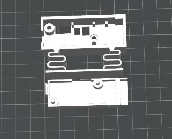
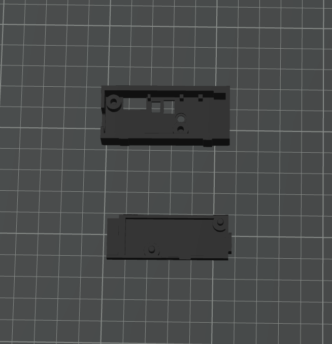
- Step 1: Print the control board PCB casing. Print file download from github or Maker world
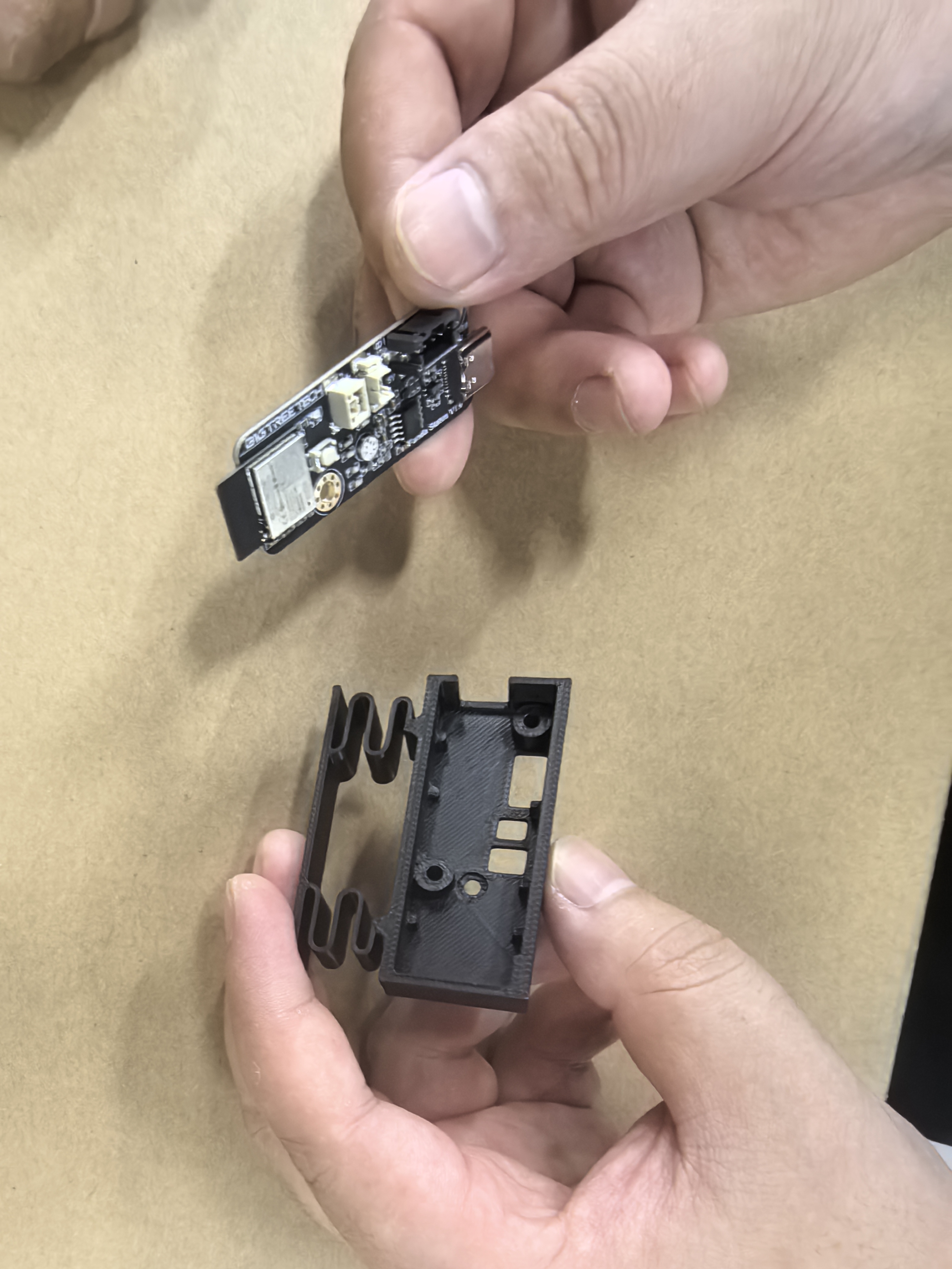
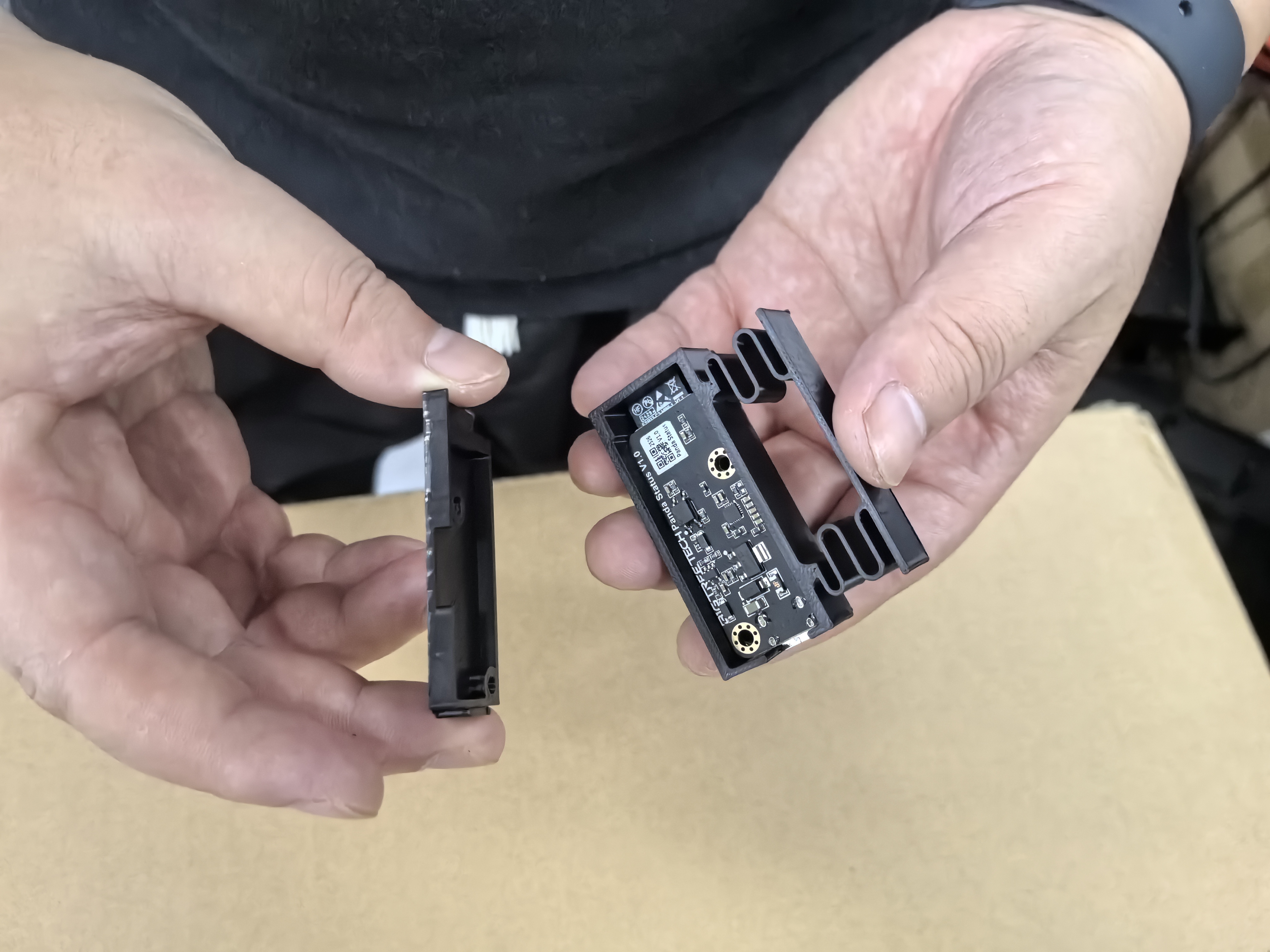
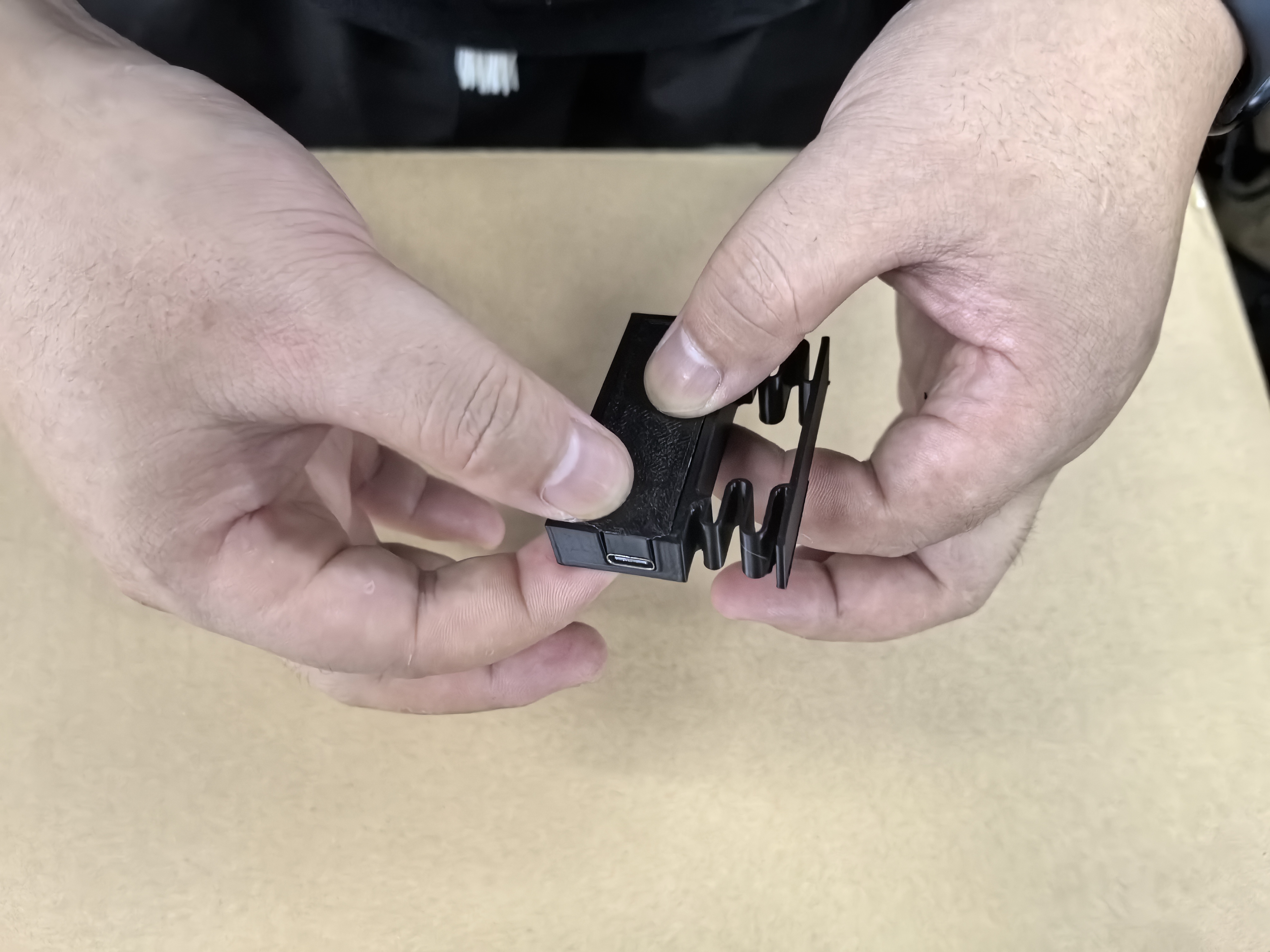
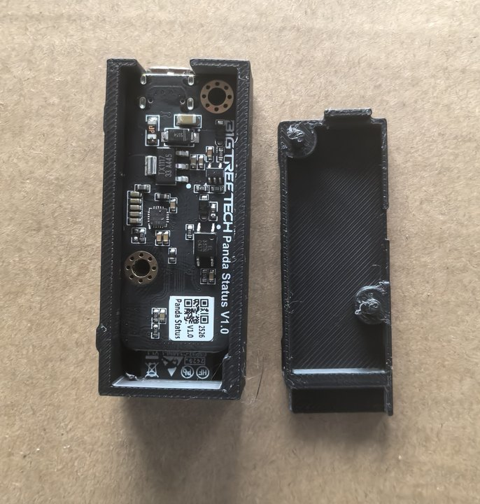
- Step 2: Install the control board into the printed casing, then securely snap on the rear cover.
- Step 3: Remove the PTFE tube silicone plug.
- Step 4: Pass the Type-C end of the power cable through the hole and connect it to the control board, which should already have the casing installed.

- Step 5: Install the printed casing into the printer (compress the spring to insert it, then release it to secure the casing in place. Push it to the right until it reaches the approximate position shown in the image below). Connect the power cable for the Panda Status.


- Step 6: Secure the Type-C power cable and reinsert the silicone plug (leave one end of the silicone plug unsecured).
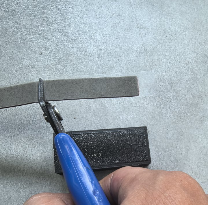
- Step 7: Secure the Panda Status power cable (route the cable as shown in the image and use the included acetate tape to fix it).


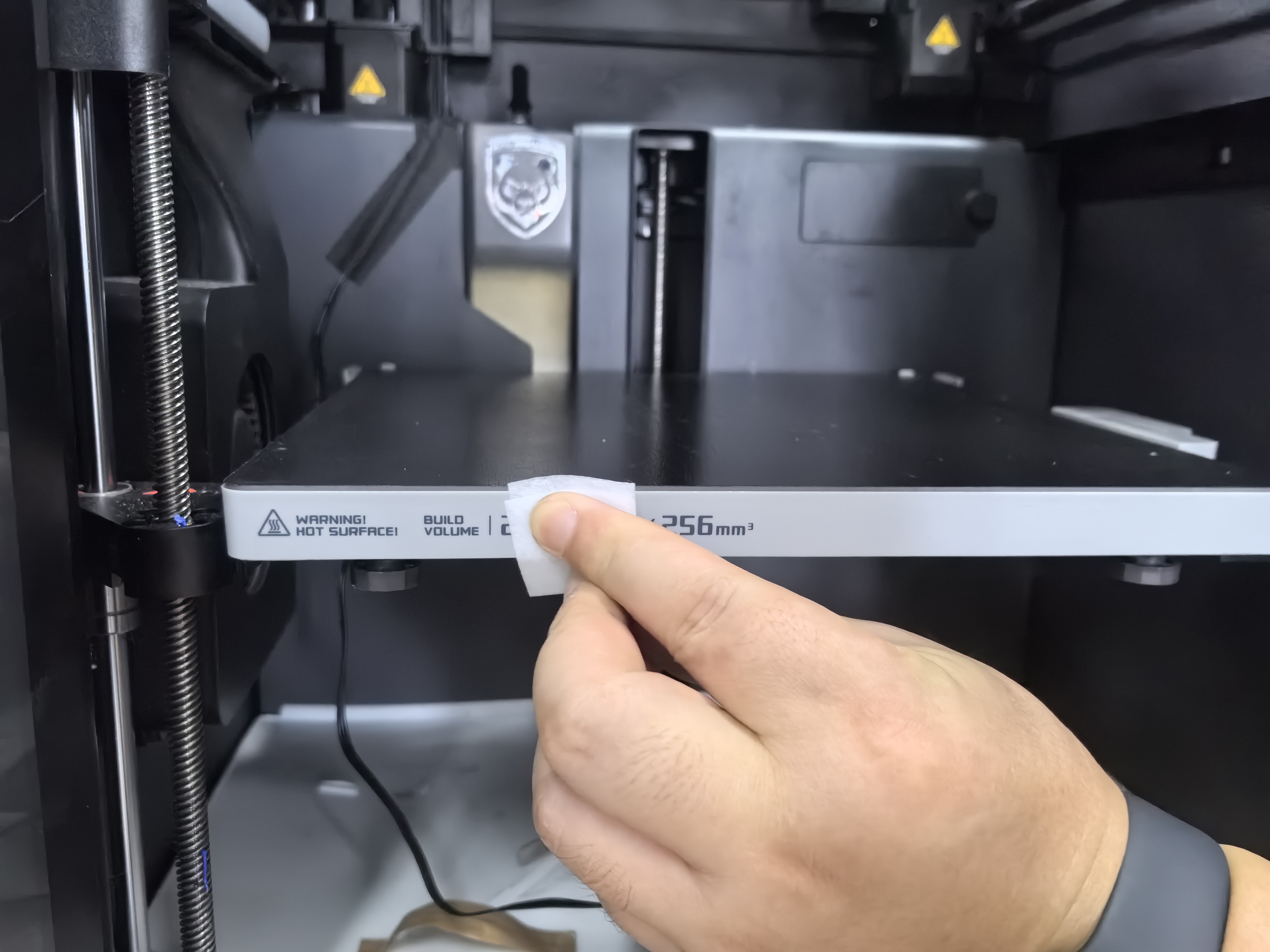
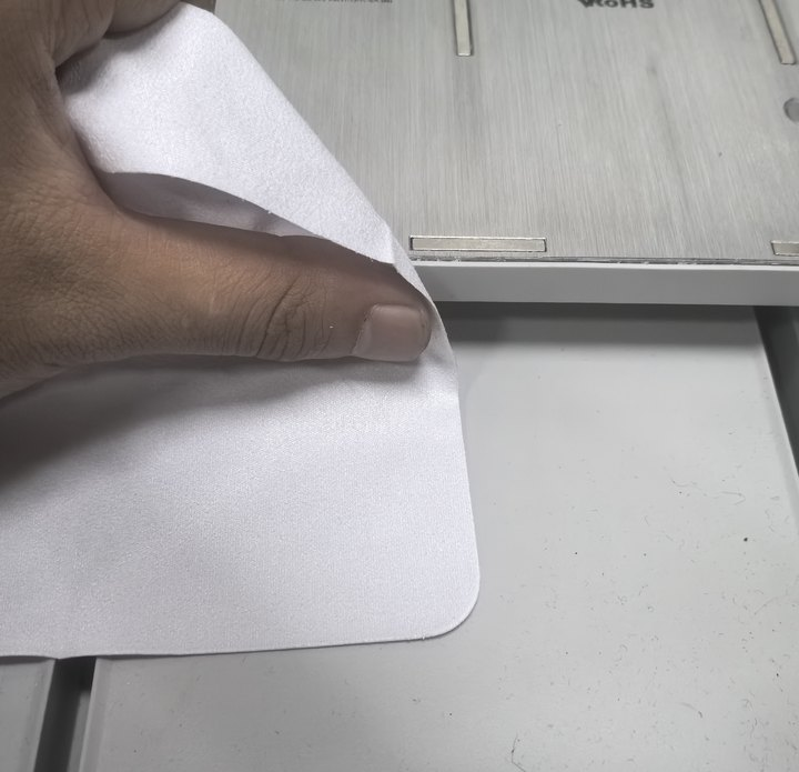
- Step 8: Raise the heated bed, then clean the installation surface with alcohol wipes and a dry cloth.

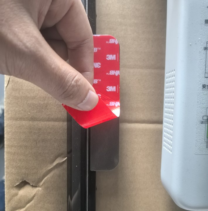
- Step 9: Plug in the Panda Status power cable, peel off the protective film from the double-sided tape, and attach the Panda Status securely to the front of the heated bed (the best adhesion is achieved after 24 hours).


- Step 10: Route the cables beneath the heated bed (as shown in the image).

Bambu Lab A1
- Step 1: Print the controller casing. Print file download from github or Maker world
- Step 2: Install the controller board into the printed casing and securely snap the back cover into place.
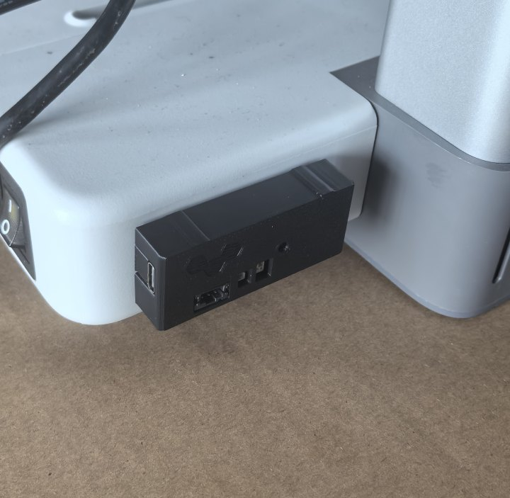
- Step 3: Mount the printed casing to the back of the printer (use the longer strip of double‑sided tape included in the kit as the backing adhesive for the casing).

- Step 4: Move the heated bed toward the back of the printer (from the printer's perspective) and clean the mounting surface with an alcohol wipe, then a dry cloth.
- Step 5: Plug in the Panda Status power cable. Peel off the protective film from the double-sided tape and press the Panda Status firmly onto the front of the heated bed.
Full bond strength is achieved after 24 hours.
- Step 6: Cut acetate tape to the appropriate length and use it to route and secure the cables along the underside of the heated bed (as shown).

- Step 7: Connect the Panda Status power cable and the controller power cable to the controller board.

Installation Guide
Bambu Lab PX Series Hidden Wiring Installation
(⚠️This method provides a fully hidden wiring solution. Since the process is more complex and involves some hands-on work, we recommend proceeding only if you feel confident with the steps.)
⚠️Please make sure the printer is powered off before beginning the following steps.
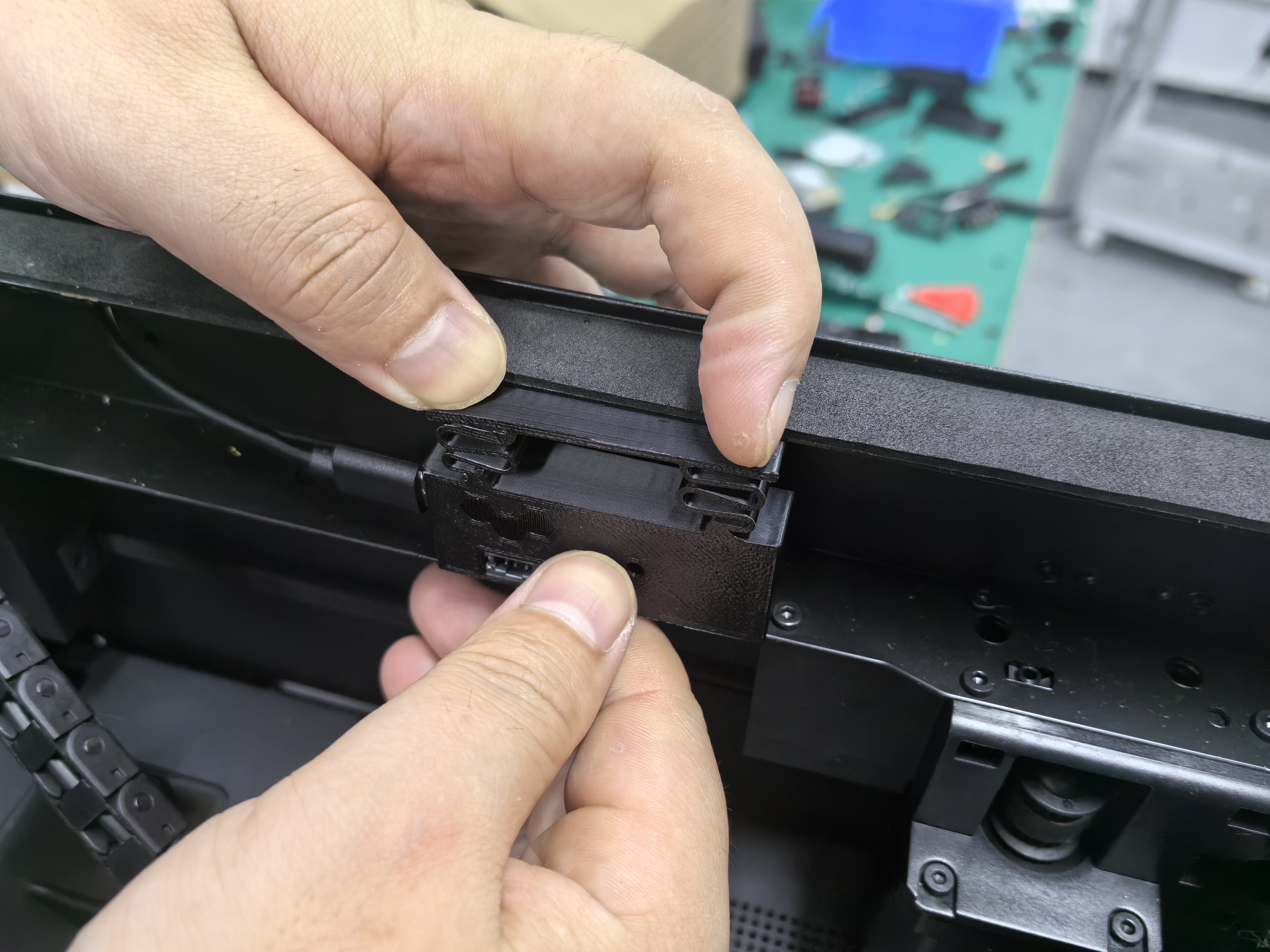
- Step 1: Print the Control Board PCB Housing

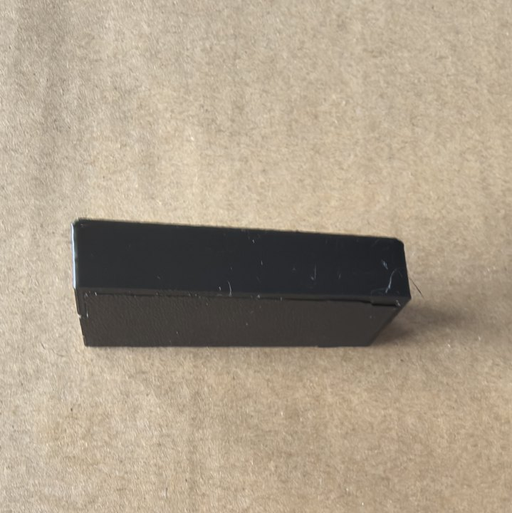
- Step 2: Install the control board into the printed housing. Snap the back cover securely into place, then attach the included double-sided tape to the back of the housing as shown.

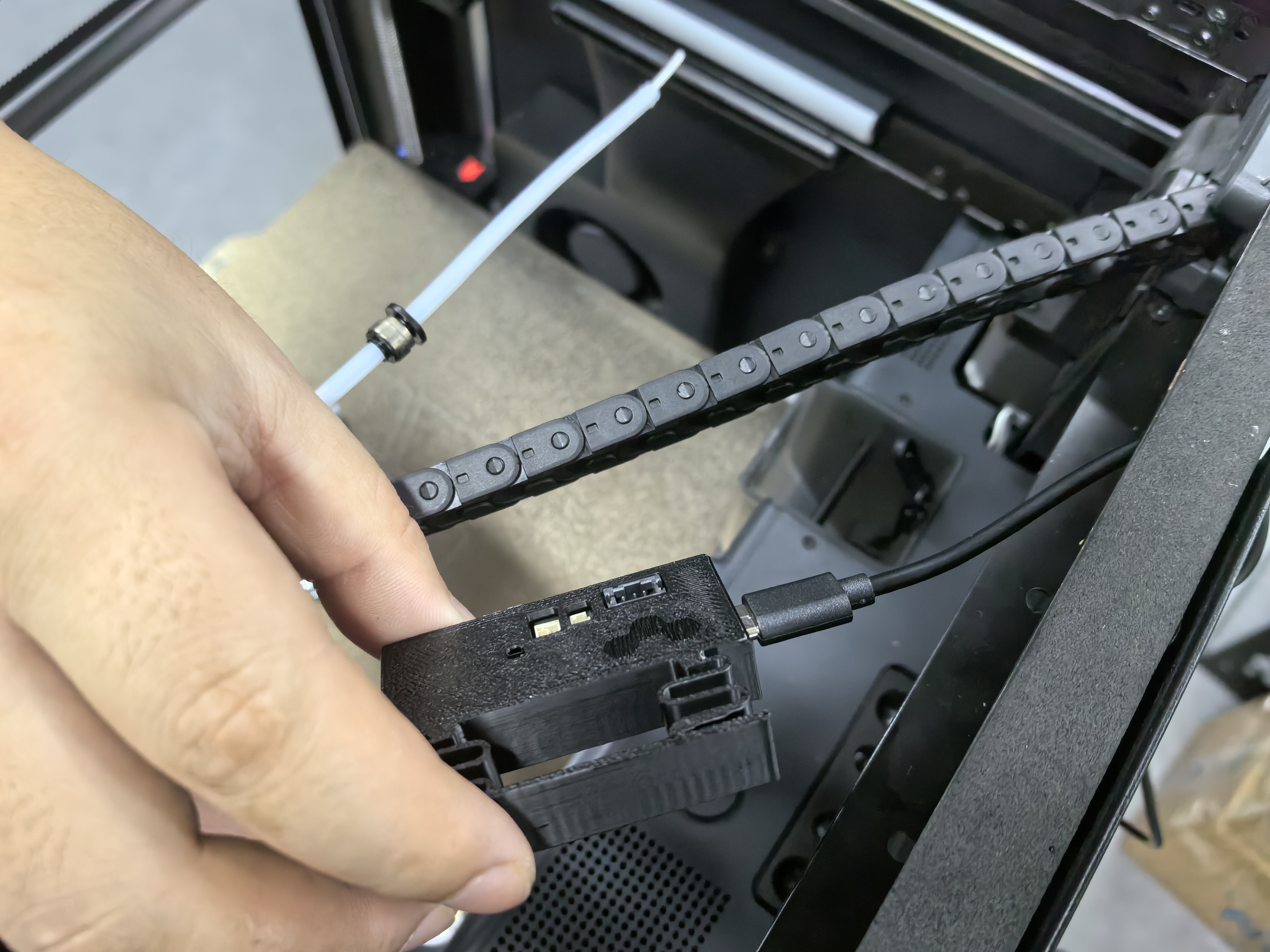
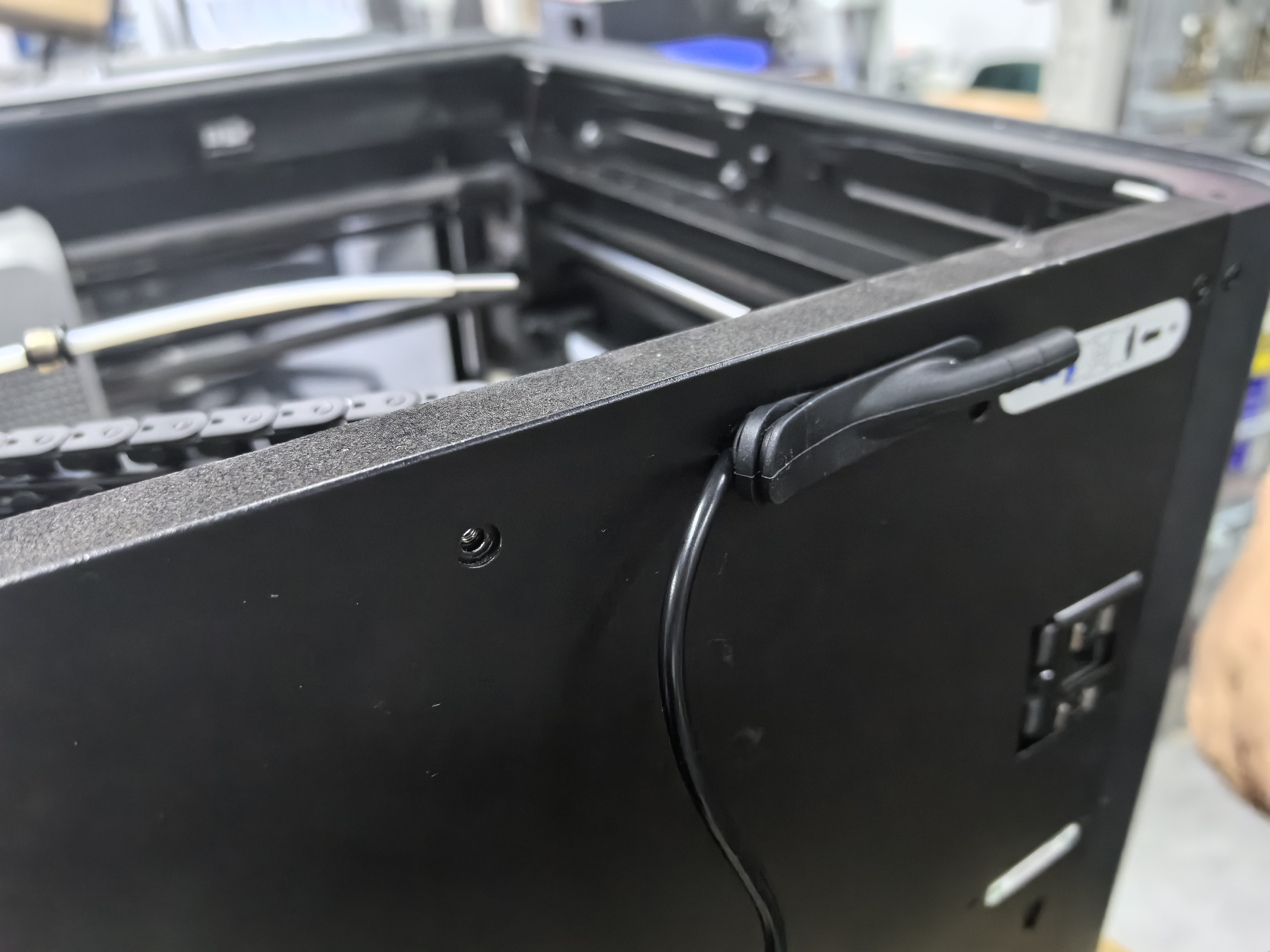
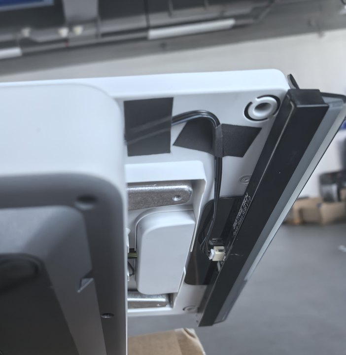
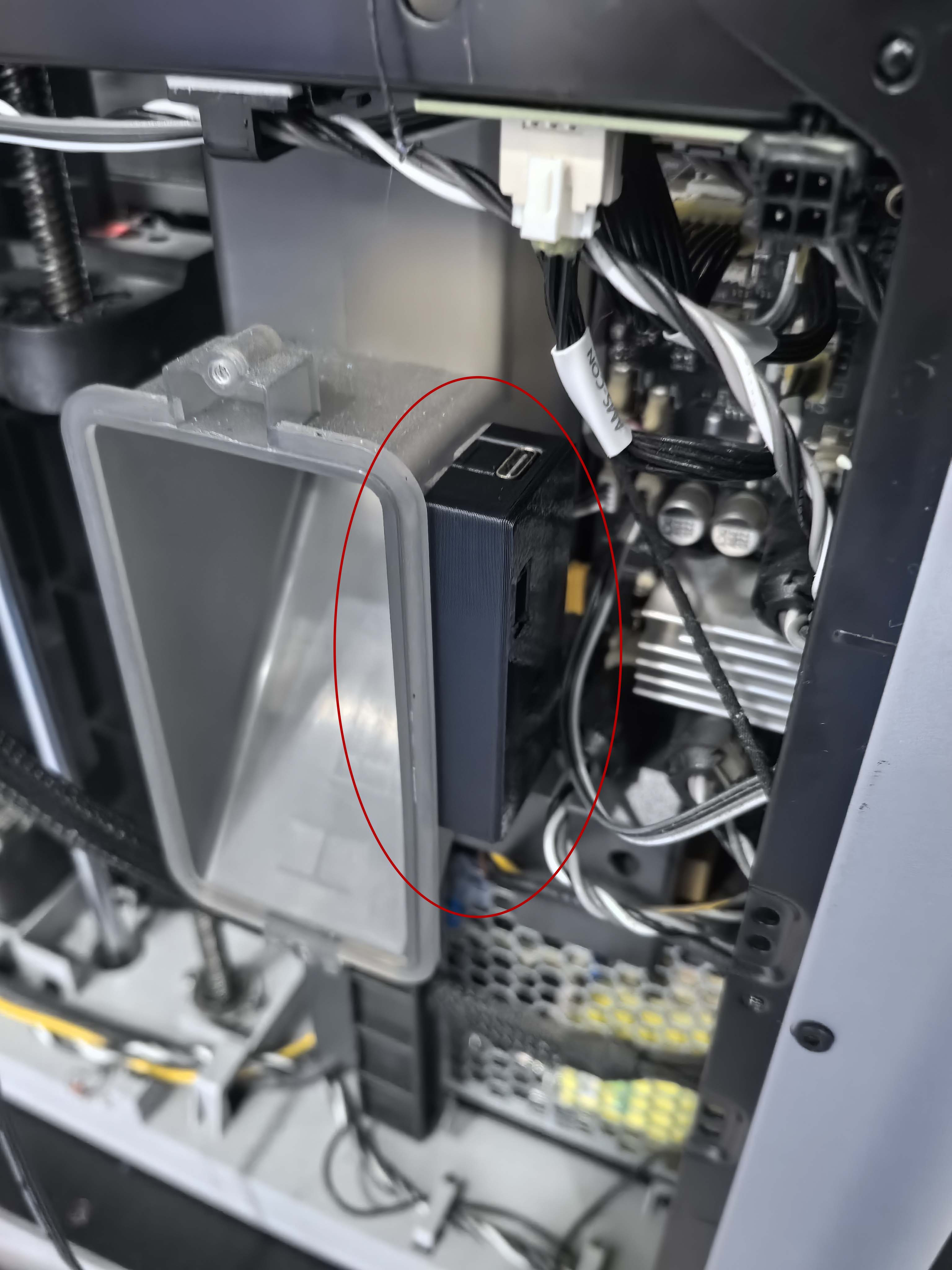
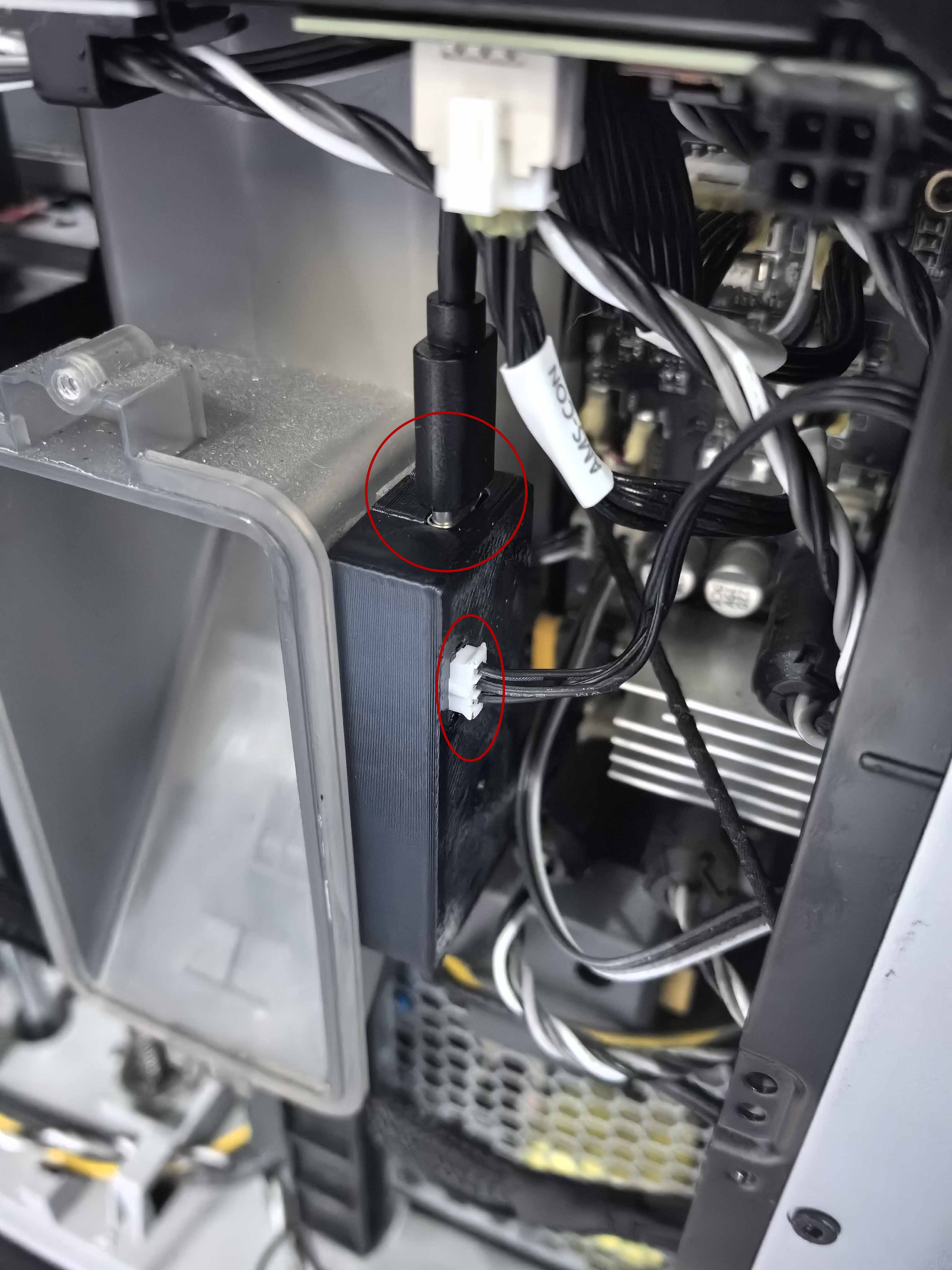
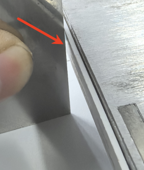
- Step 3: Remove the rear panel of the printer. Attach the printed housing to the outer wall of the waste chute as shown, making sure the Type-C power port faces upward.
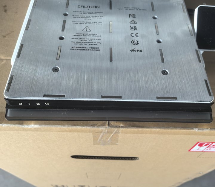
- Step 4: Raise the heated bed. Clean the mounting surface with an alcohol wipe followed by a dry cloth.
- Remove the protective film from the double-sided tape, then press the Panda Status firmly onto the front of the heated bed as shown.
Best results are achieved if left for 24 hours.
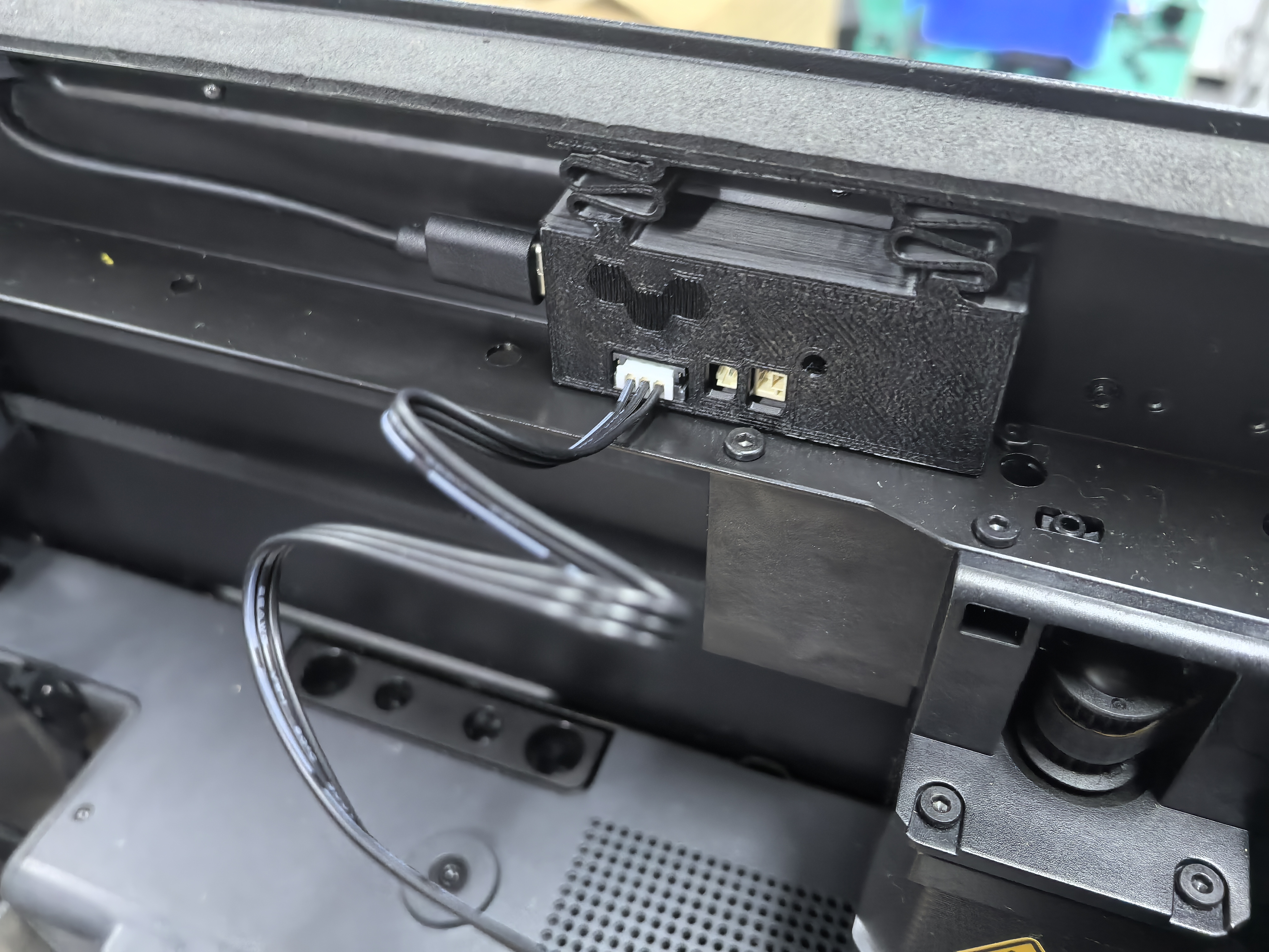
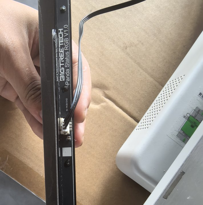
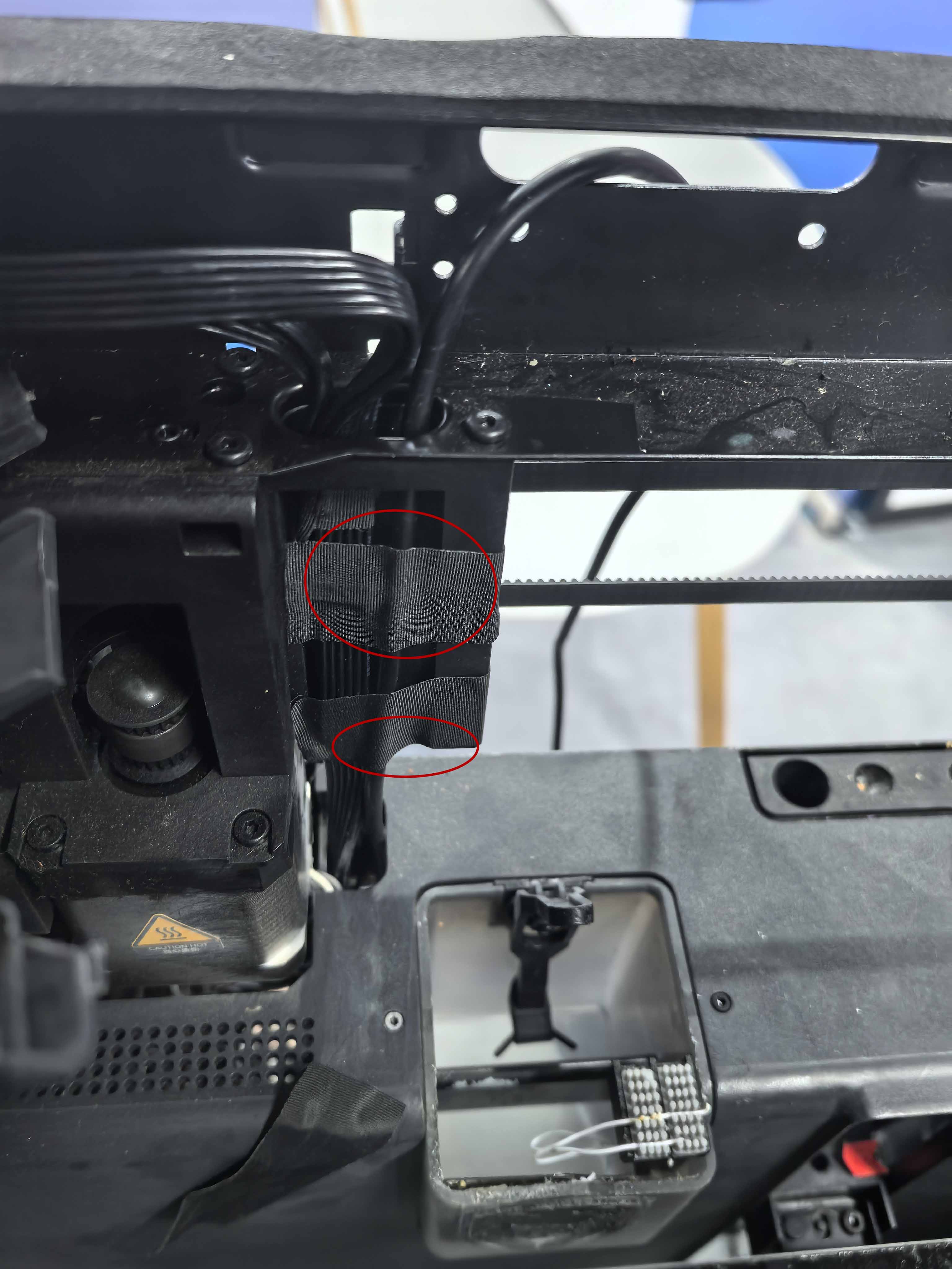
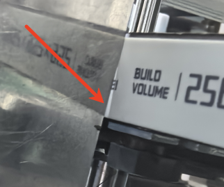
- Step 5: Route the Status control cable through the indicated position to the underside of the heated bed. Connect it to the Status light bar and secure it with acetate tape as shown.

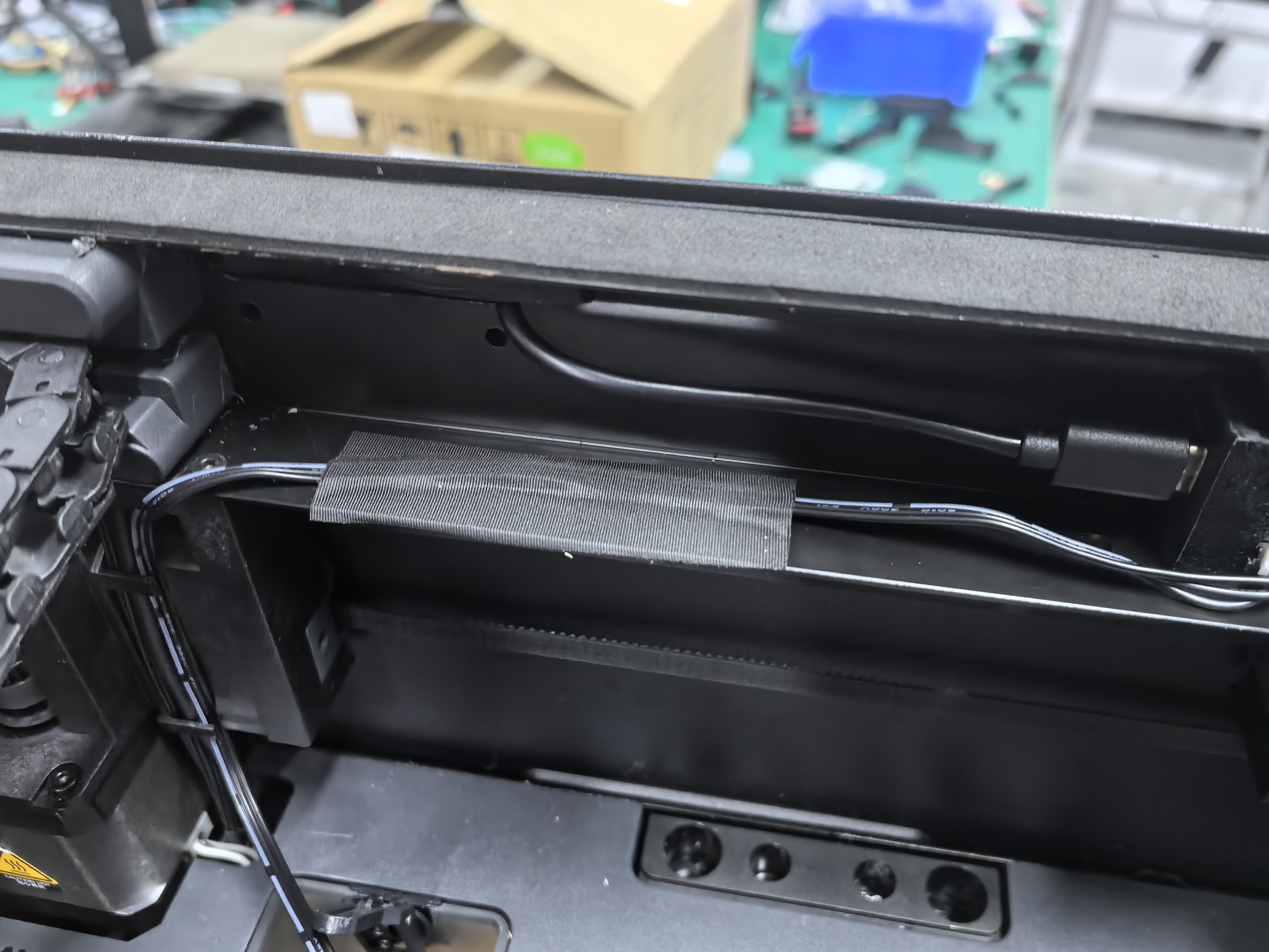
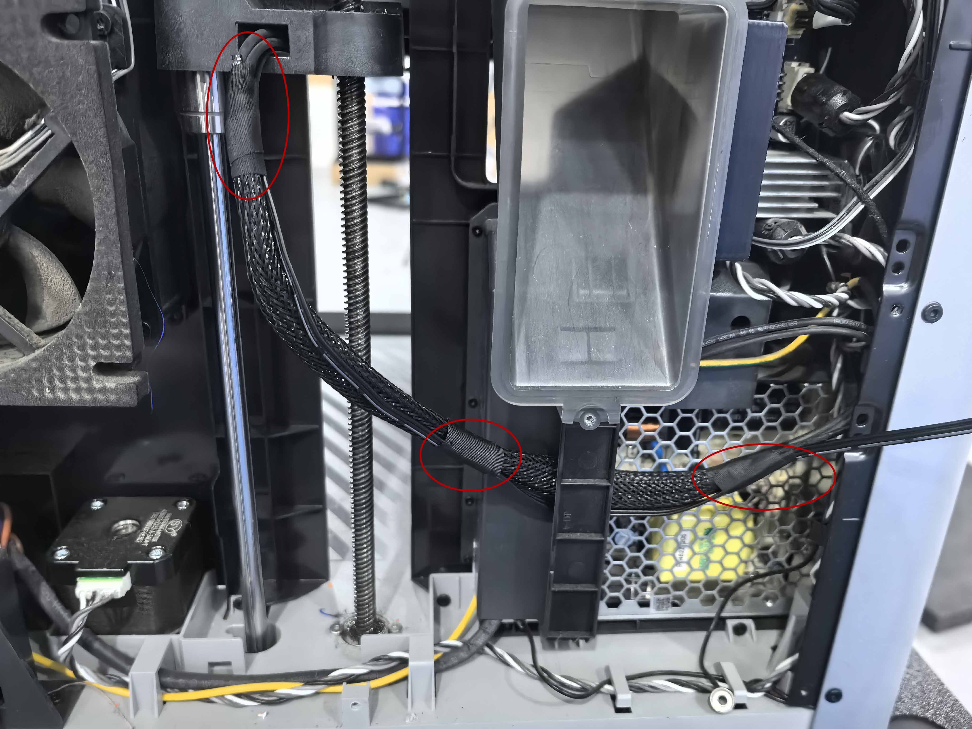
- Step 6: Bundle the Status control cable together with the heated bed wiring harness using the provided acetate tape.
Fix the bundled cables into the machine’s cable holder as shown.
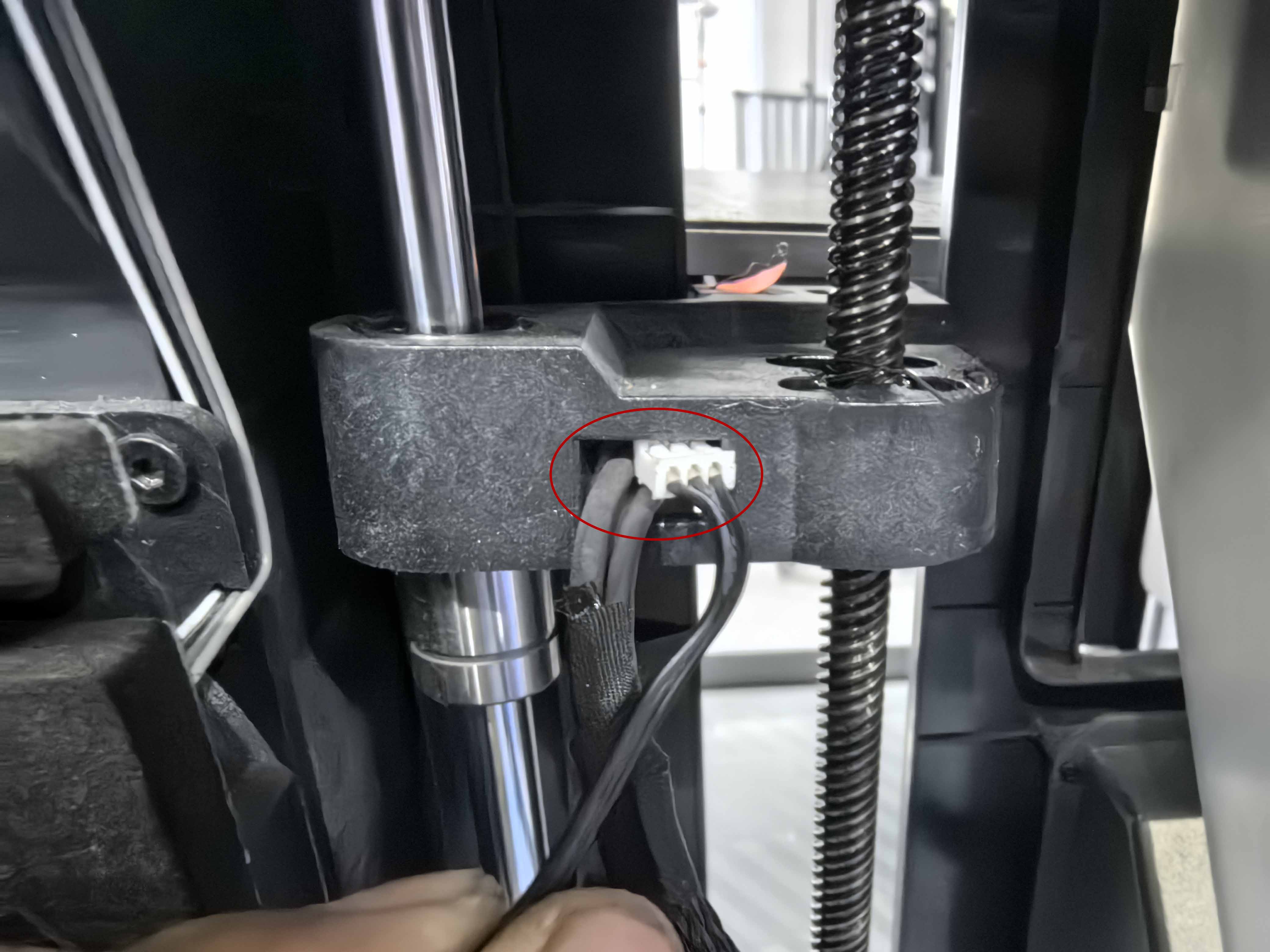
- Step 7: Plug the control cable into the control box.
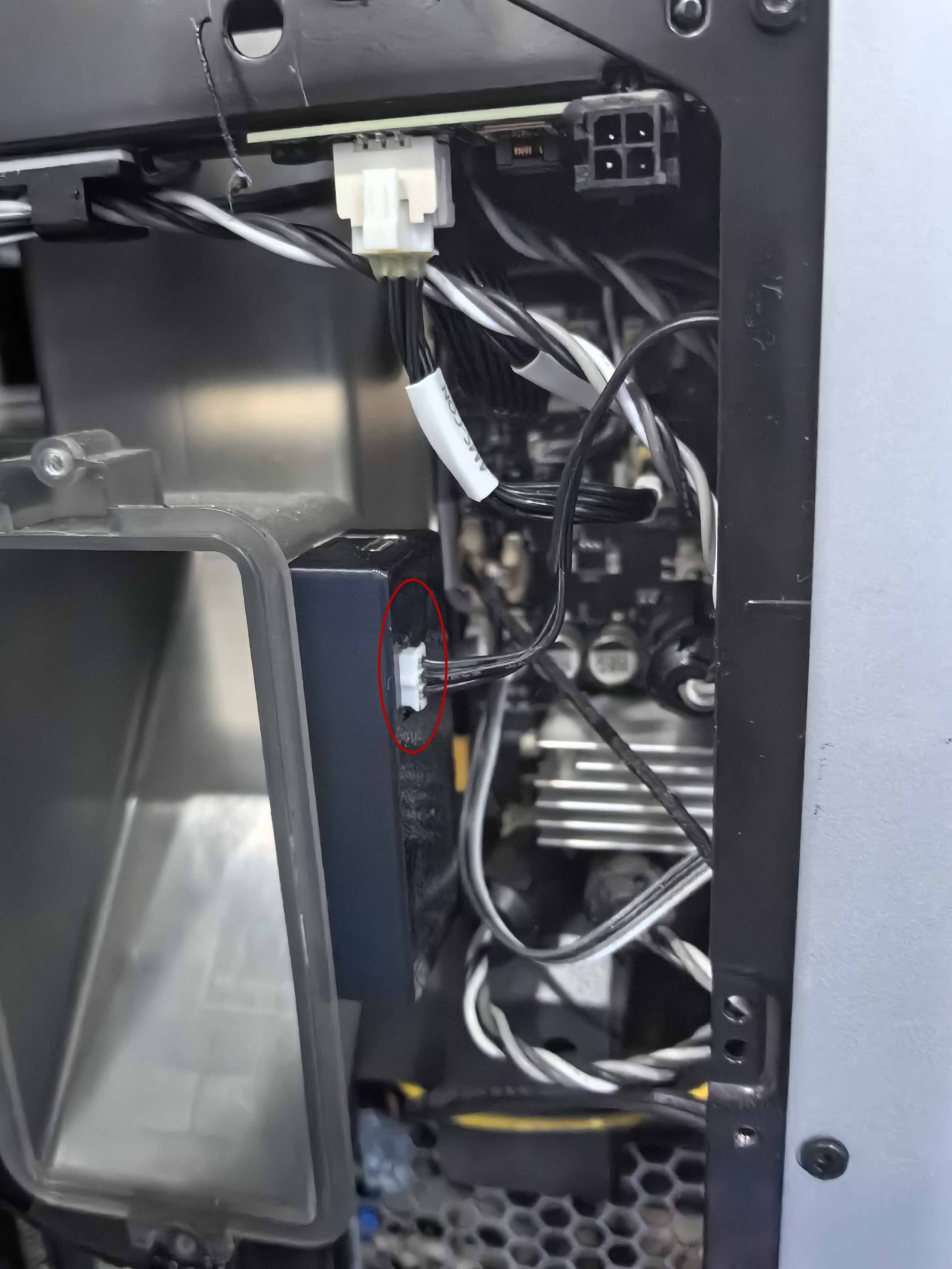
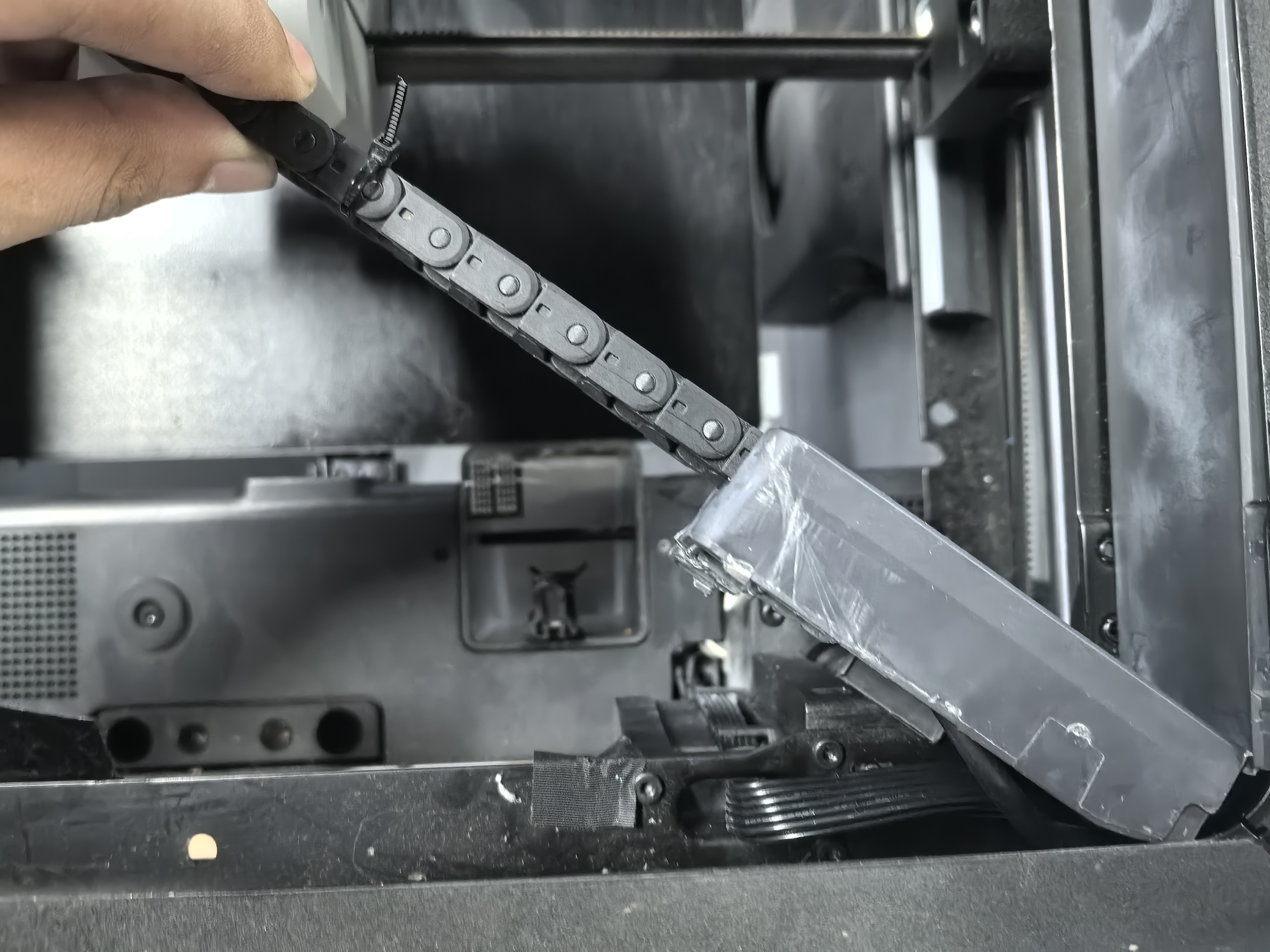
- Step 8: Remove the screw shown to detach the printer’s drag chain cable cover.

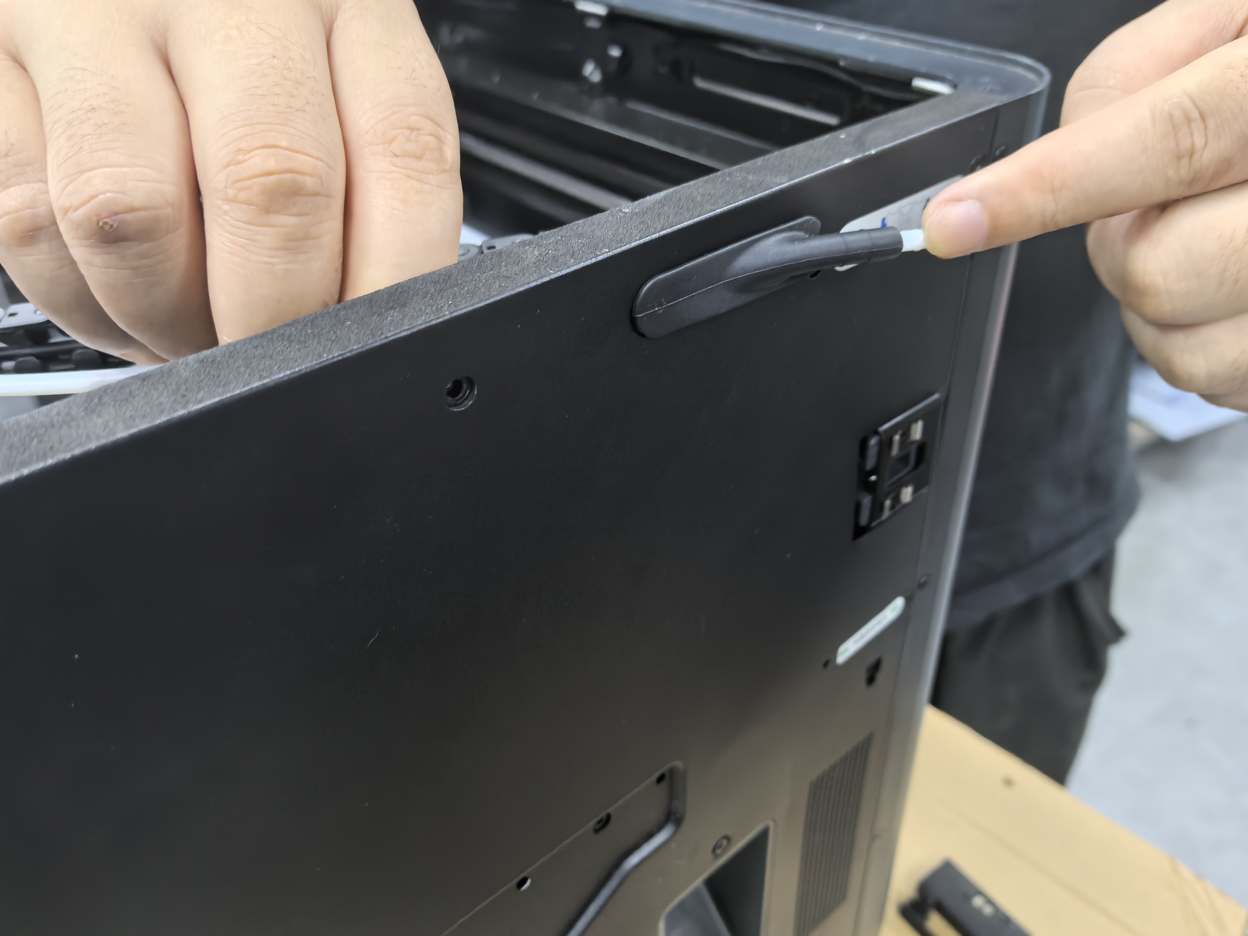
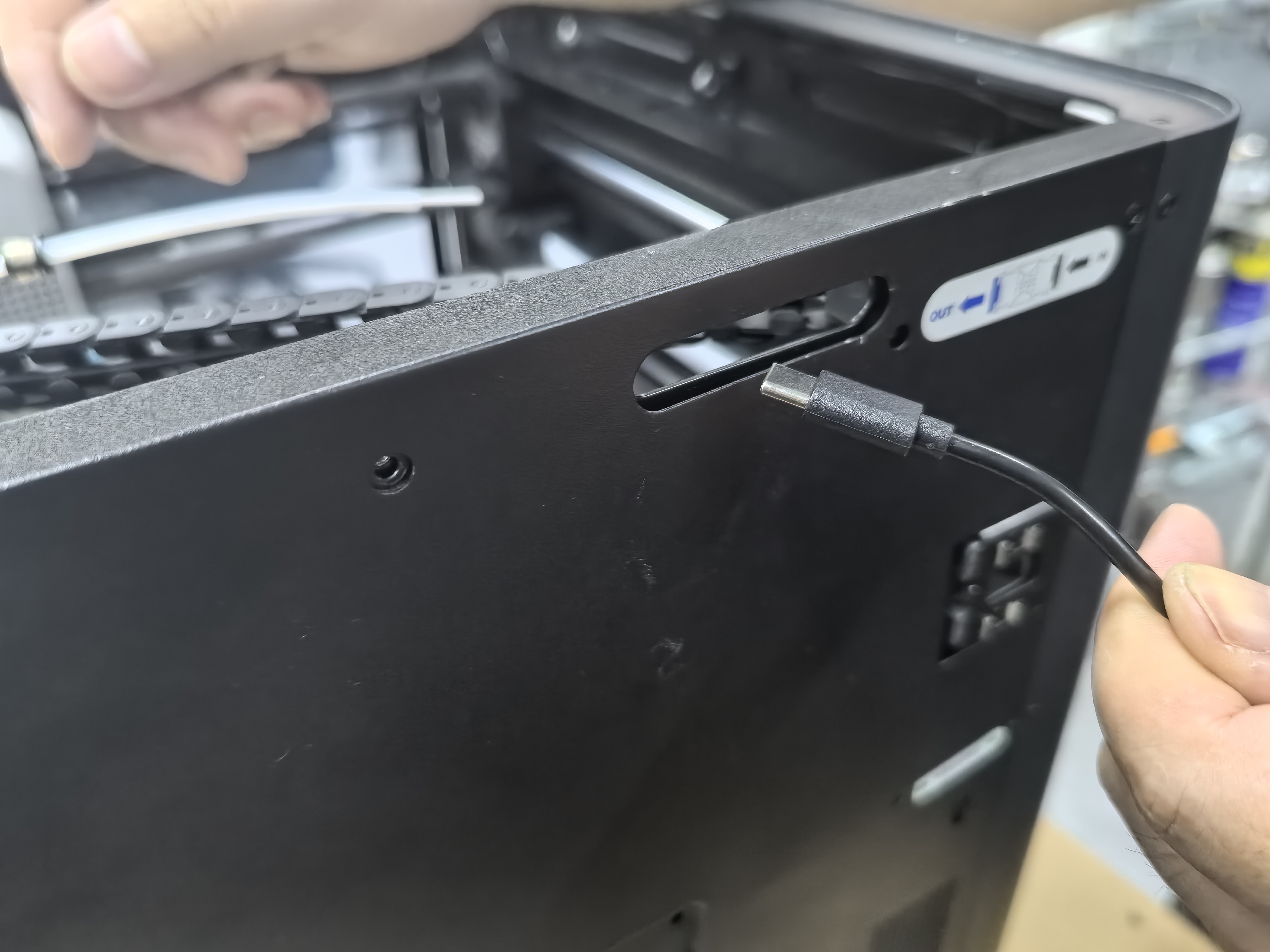
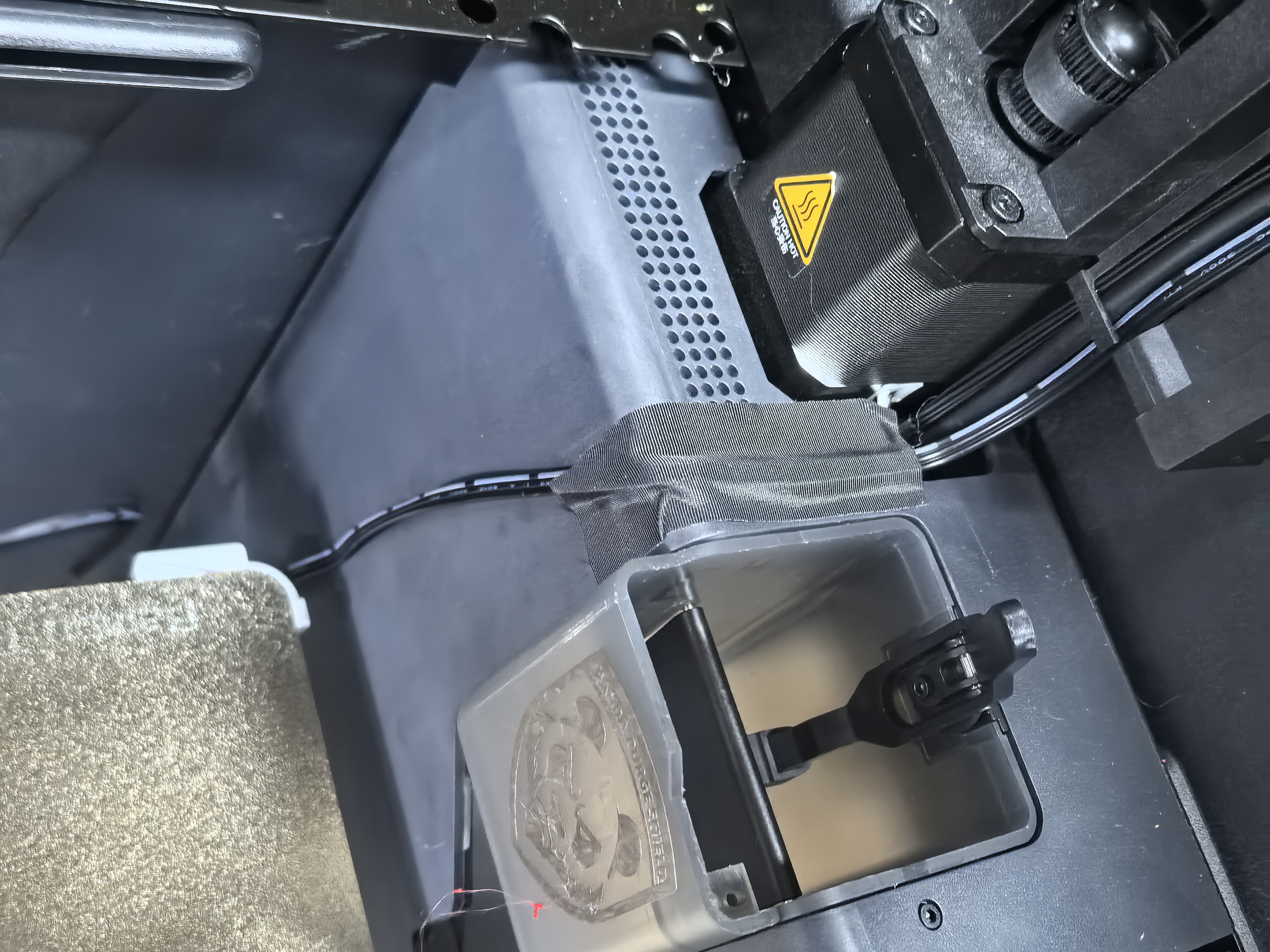
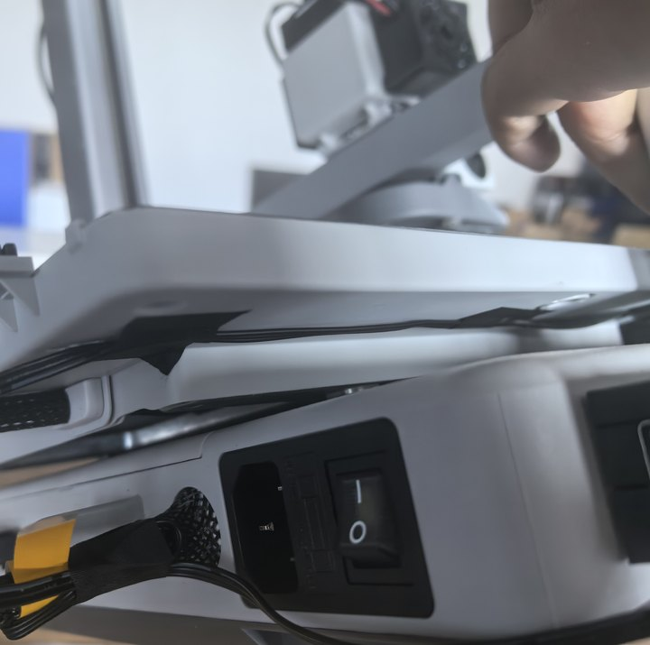
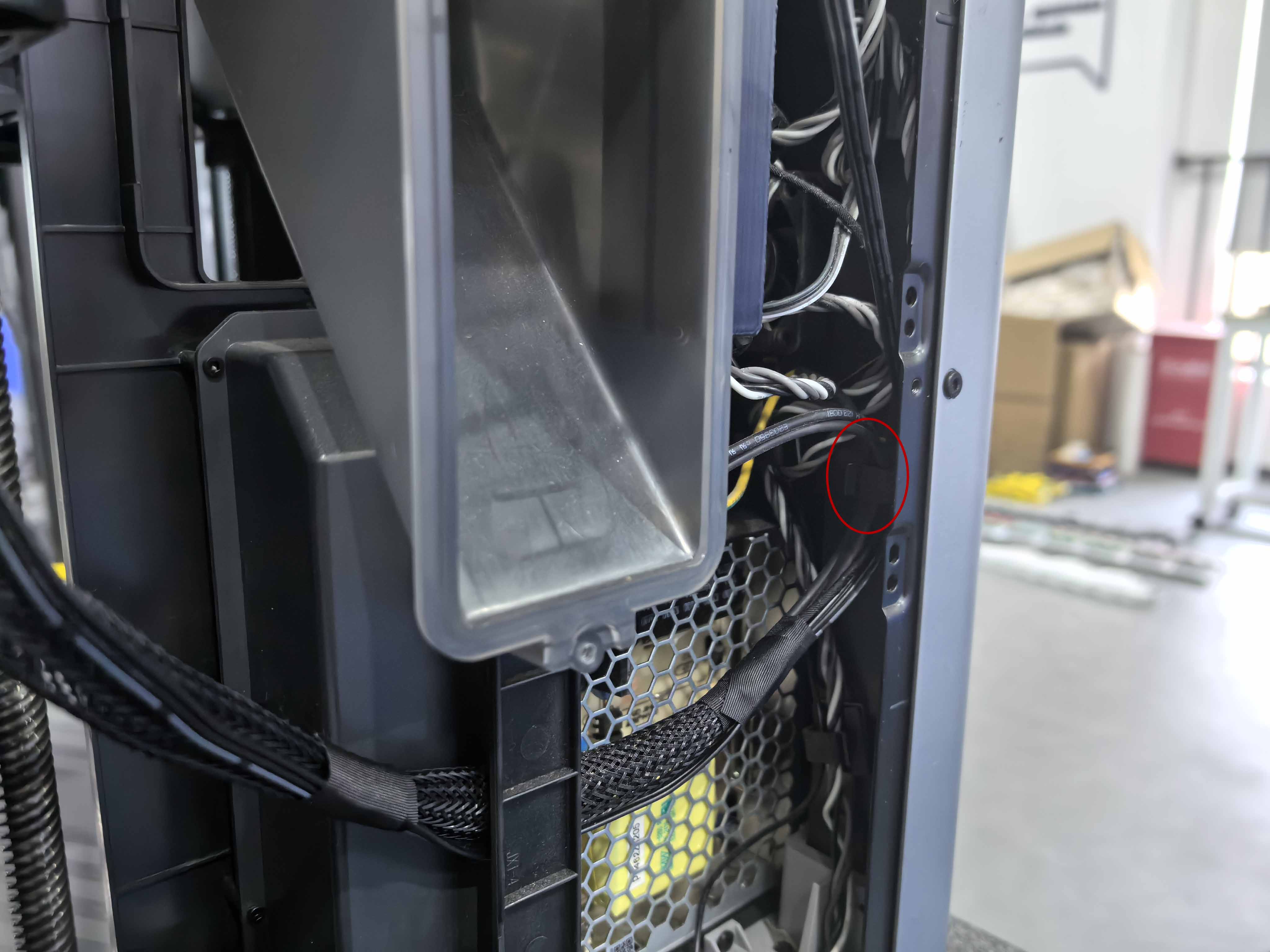
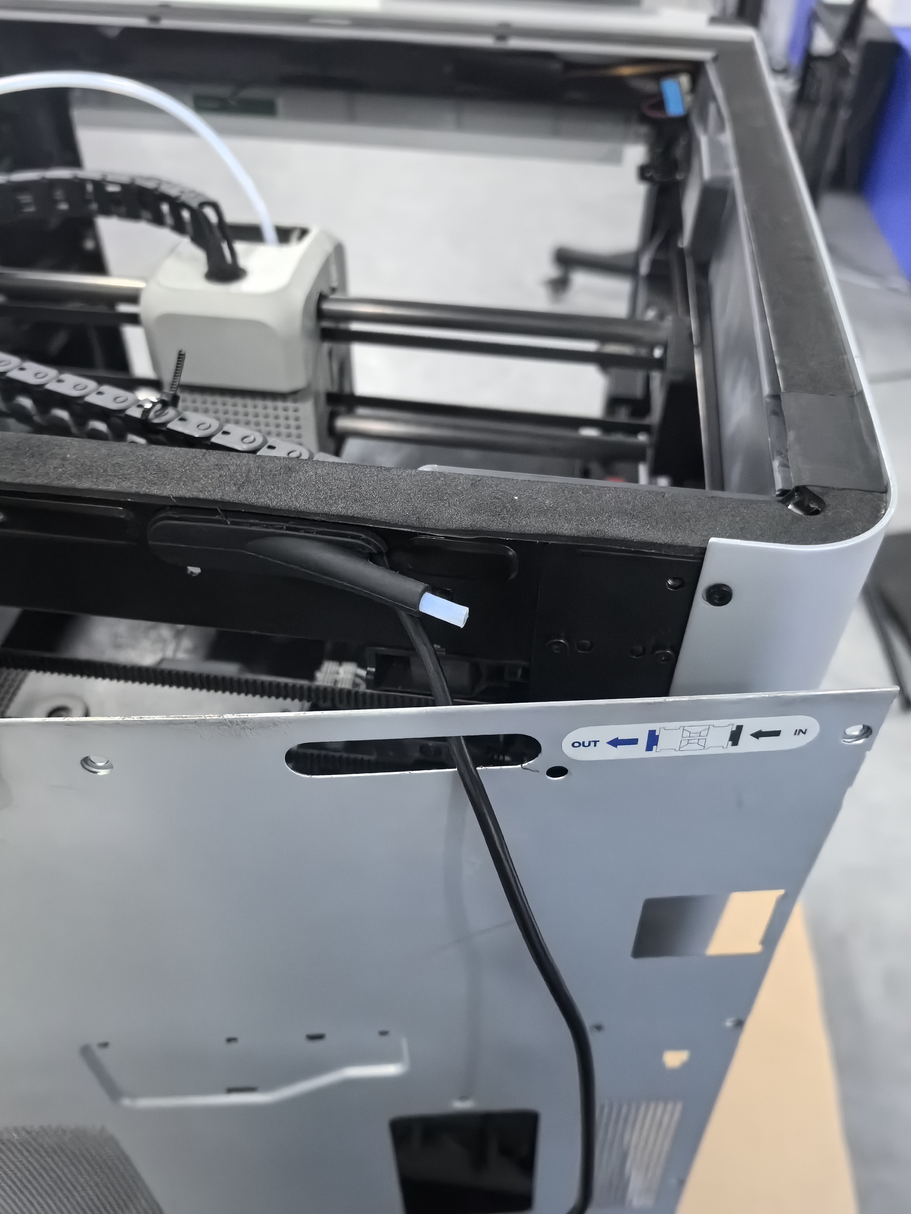
- Step 9: Route the Type-C power cable into the printer as shown, then plug it into the control box.
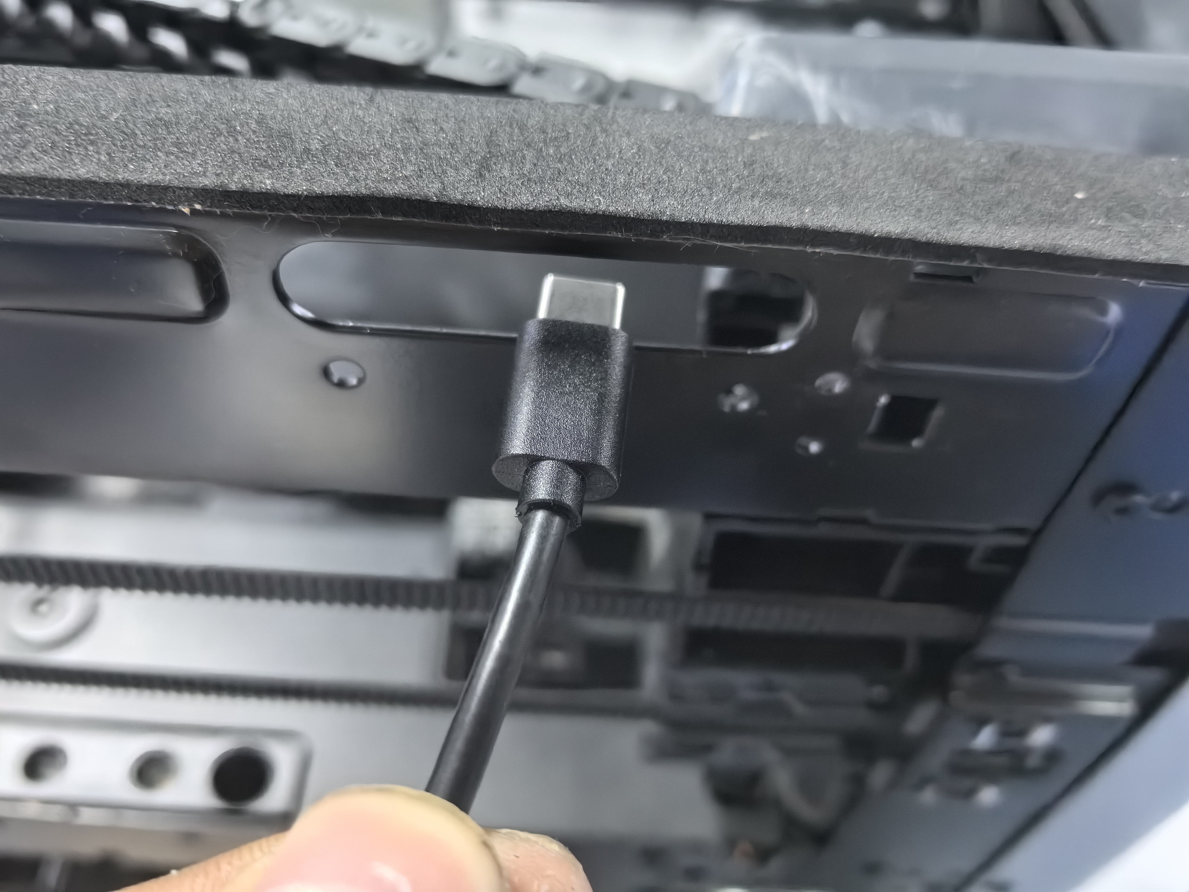
- Secure the cable with acetate tape along the routing path.
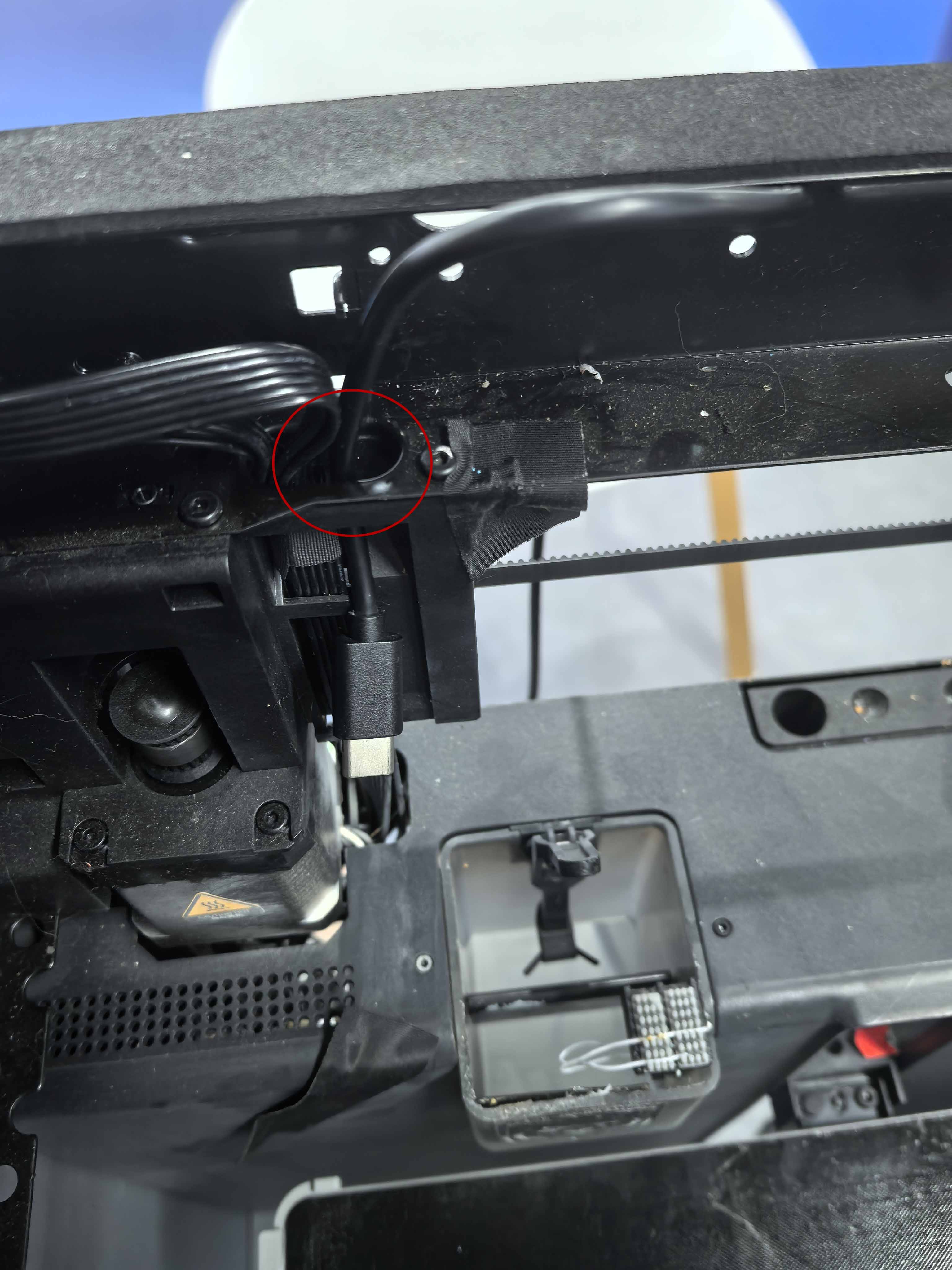
- Pass the cable through the internal opening of the cable cover to the outside of the machine as shown, then reinstall the cover and fasten it back with the previously removed screw.


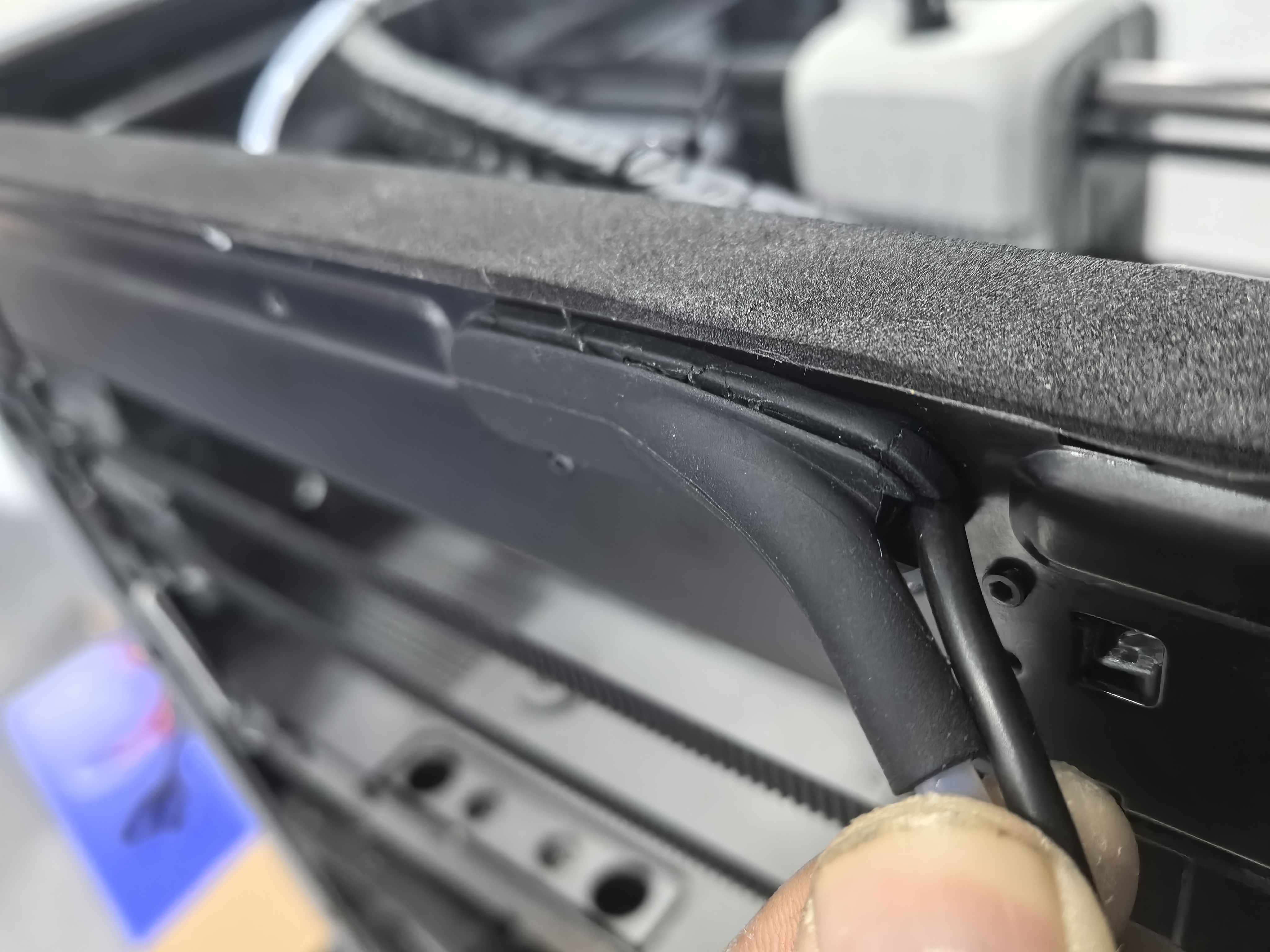
- Step 10: Replace the original plug with the included silicone plug for cable routing, as shown.
- Step 11: Route the cable out through the opening in the rear panel, then reinstall the panel.
Notes
- The accessories include spare double-sided tape, which can be stacked to install the Panda Status in other positions.

Panda Status Installation Notes
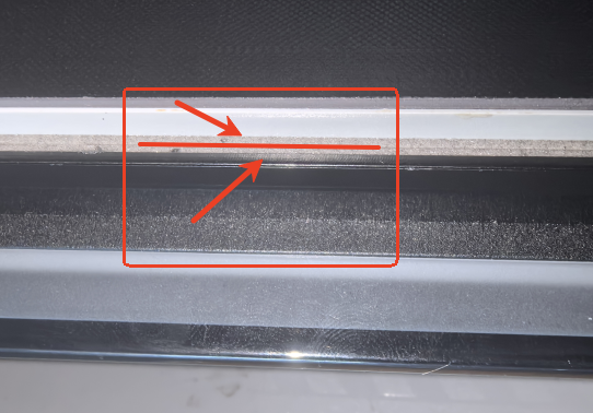
Some users may notice small gaps or less-than-perfect adhesion during installation. This is normal and may happen for a few reasons:
-
Universal design: Panda Status is made to fit A, P, and X series printers, so it uses a more general size.
-
Heatbed angle differences: The vertical angle of the A1 heated bed is slightly different from that of the PX series.
And, on some PX printers, slight differences in the leveling knob positions under the heatbed can affect how well the Status light bar fits.
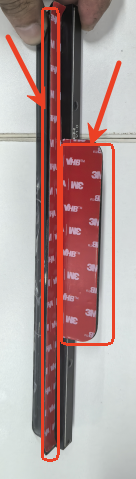
- The Status light bar has two contact surfaces as shown, and in practice, attaching only one side is usually enough to hold it firmly.
-
Improving the Fit
-
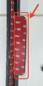
Apply double-sided tape only to the bottom side. (This provides sufficient strength but may leave a visible gap in front.)
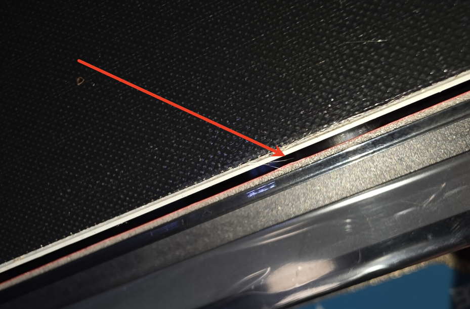
- For improved appearance, use the spare double-sided tape included in the package (prepared specifically for this issue). Apply tape to both angled contact surfaces of the Status light bar before attaching it to the heated bed.
First Connection
When you power up for the first time or restore factory settings, you'll see a blue flowing light, indicating that Panda Status is not yet bound to the printer.
WiFi Connection Guide
-
Connecting to the Panda Status's WiFi_AP Hotspot
-
Connect to the Panda_Status AP hotspot:
Panda_Status_XXXXXXXXXX. The default password is987654321.
-
Accessing the AP Webpage
-
After connecting to the AP, open a browser on your computer and enter the default IP address:
192.168.4.1. On mobile devices, the Panda_Status Web UI will automatically appear, or you can manually enter the IP address in the browser:192.168.4.1. For Computer:
For Mobile:

-
Select Language (Default: English)
-
After selecting a language, click
Next.
-
WiFi Connection Page
-
Scanning for WiFi
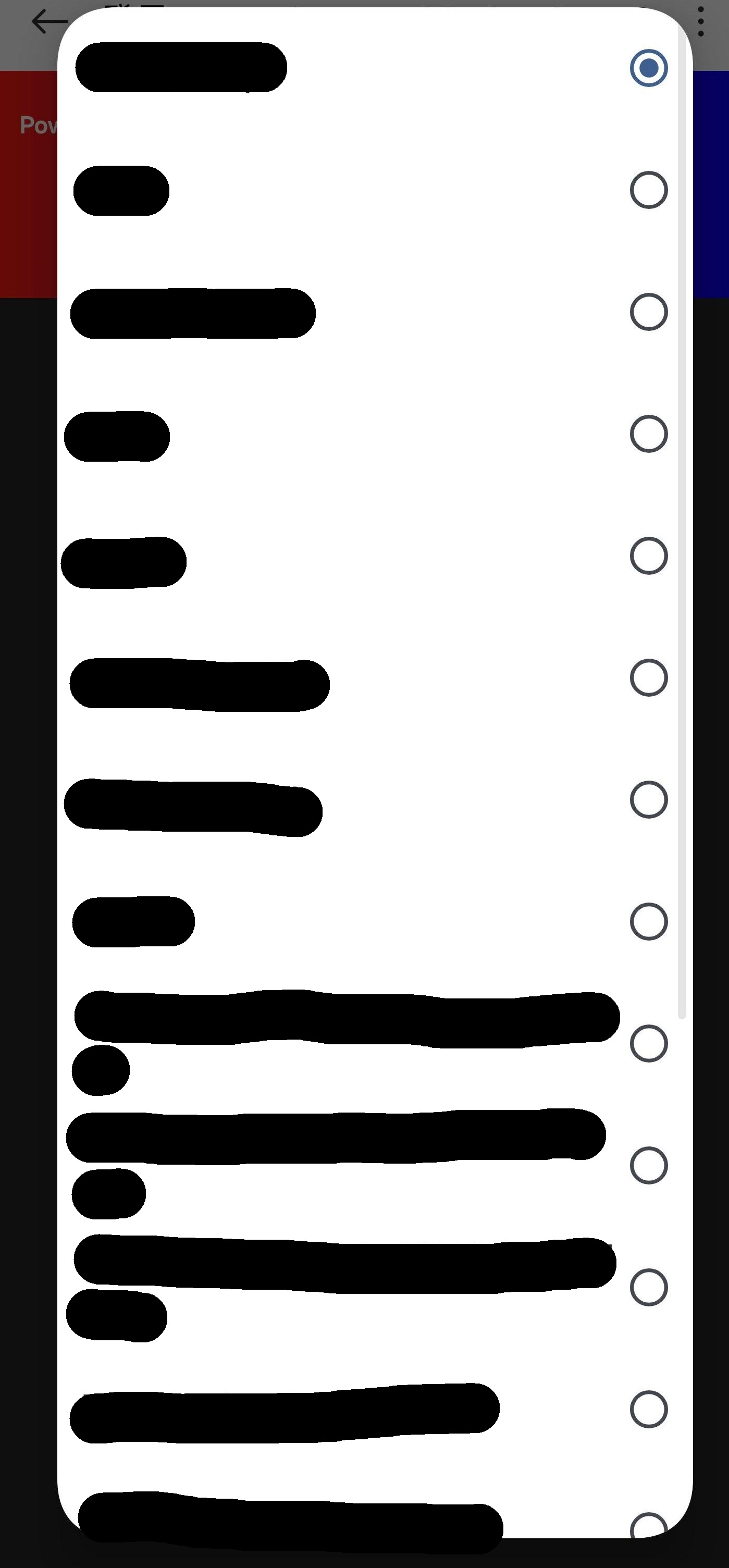
After the initial setup or a factory reset, this page will automatically scan for available WiFi networks.

Once the scan is complete, a pop-up will appear notifying you that the scan is finished.

Select the WiFi network you want to connect to.
-
Connecting to WiFi
Type your password and tap the
eye iconif you'd like to see the password you've entered.
Click Connect, and the interface will switch to the WiFi connection page, showing
Connecting to WiFi.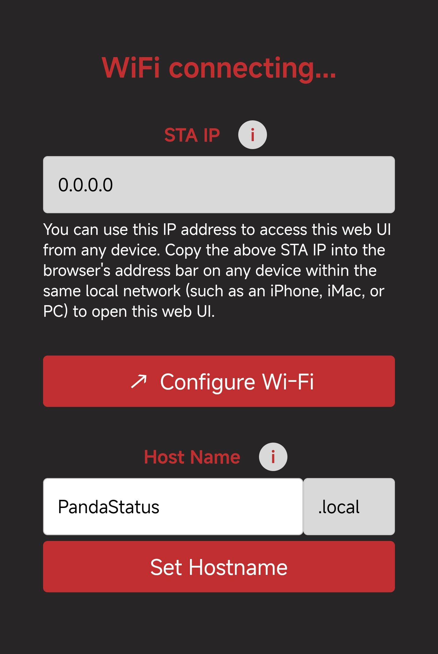
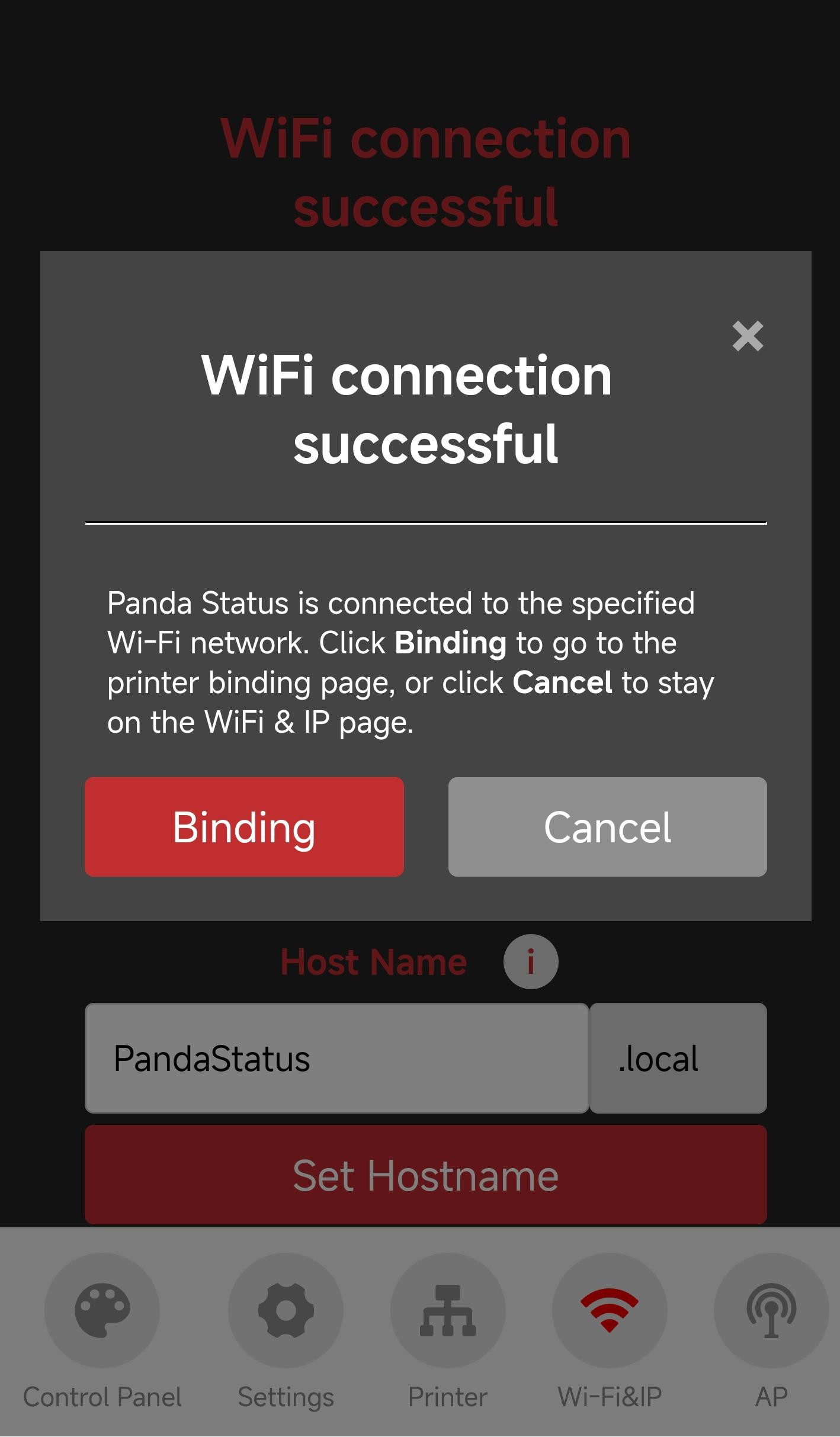
Wait a moment, and a WiFi connection status pop-up will appear.
- Connection Failed:

- Connection Successful: You can either
bind the printerand proceed to the printer interface or clickCancelto stay on the WiFi page.
Printer Binding Page
- Elements and Functions

- ① Printer Page Selection: When you click the icon, it will turn red to indicate that you are on the Printer page.
- ② Scan for Printers on the Same Local Network
- ③ Select the Detected Printer
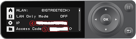
- ④ Enter Printer's SN Code
- ⑤ Enter Printer's Access Code
- ⑥ Enter Printer's IP Address
-
⑦ Confirm to Bind This Printer
-
How to Bind a Printer (Using P1P as an Example)
Click Scan button. After a short wait, a pop-up will appear confirming that the scan was successful.

Select the printer from the list. The printer's SN code and IP address will automatically fill in.

Enter the printer's access code: Find the access code in the printer's settings, enter it in the box, and click Bind to successfully bind the printer.


Webpage Usage Guide
WiFi Page
- Elements and Functions
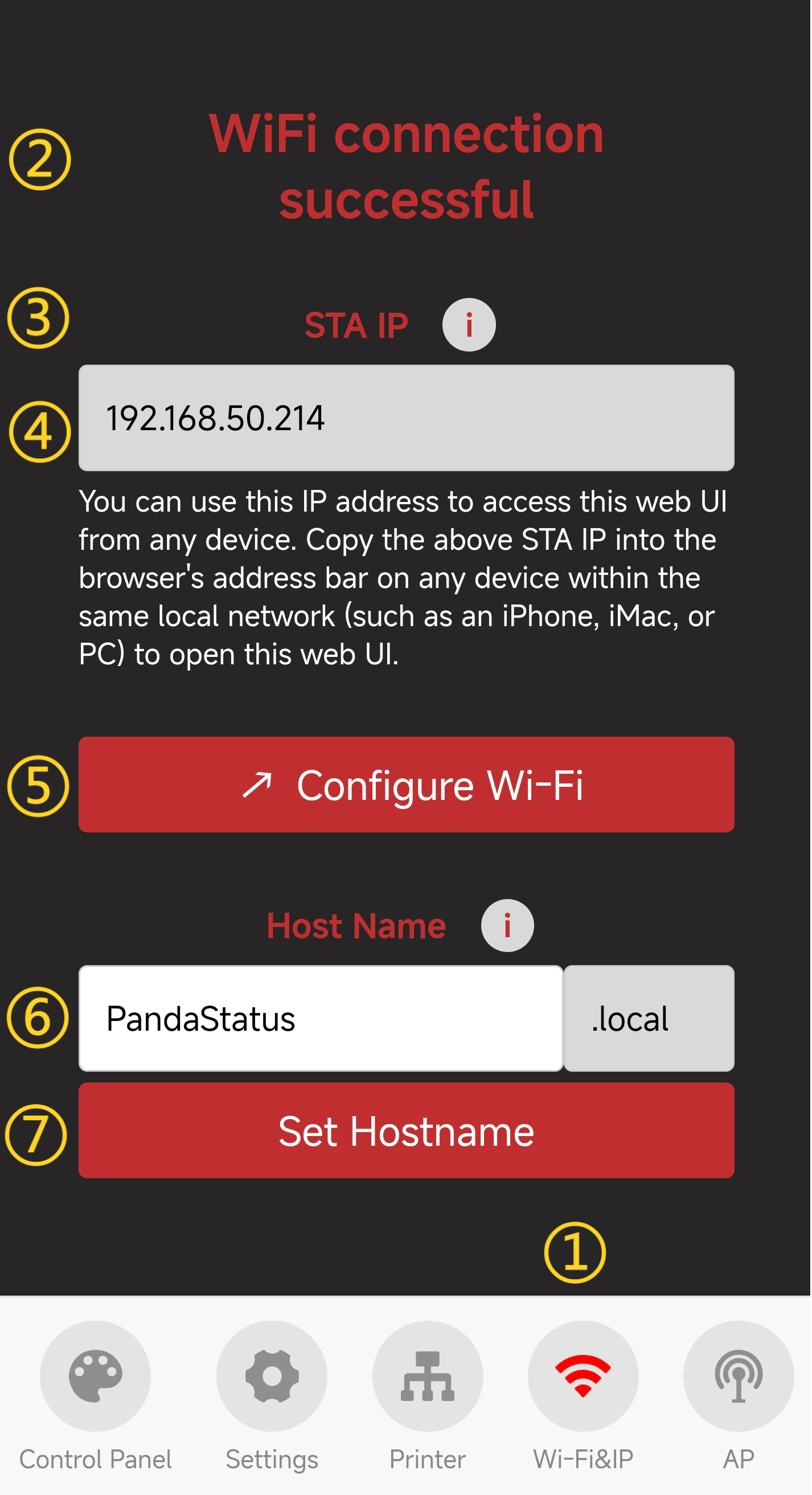
- ① WiFi Page Selection: When you click the icon, it will turn red to indicate that you are on the WiFi page.
- ② Current WiFi Connection Status
- ③ IP Address Icon: Click the icon to display a pop-up. If the IP field is blank, ensure Panda_Status shows "Connected." If it says, "Not Connected," check your network settings.
- ④ IP Address Display: Entering this IP in your browser will take you to the Web page, as long as you're on the same local network.
- ⑤ WiFi Network Configuration Button: Click to go to the WiFi connection page
- ⑥ Host Name: The default hostname is "PandaStatus." If you forget the IP, you can use the hostname followed by "local" in the browser (e.g., http://PandaStatus.local). To modify the hostname, click the text box to edit it, then click "Set Hostname" to confirm.
- ⑦ Confirm Hostname Modification
AP Page
- Elements and Functions

- ① AP Page Selection: When you click the icon, it will turn red to indicate that you are on the AP page.
- ② AP Hotspot Switch
- ③ AP Name: Default is
Panda_Status_XXXXXXXXXX - ④ AP Password: Default is
987654321 - ⑤ Hotspot IP: Default Hotspot IP is "192.168.4.1." If your router's IP range is "192.168.4.xxx," an IP conflict will prevent the device from binding to the printer. Change the Panda_Status hotspot IP to a different range.
- ⑥ Confirm Button: Clicking this will restart the device. After the restart, you can connect to the AP hotspot.(How to connect to the AP hotspot)
Settings Page
- Elements and Functions

-
① Settings Page Selection: When you click the icon, it will turn red to indicate that you are on the Settings page.
-
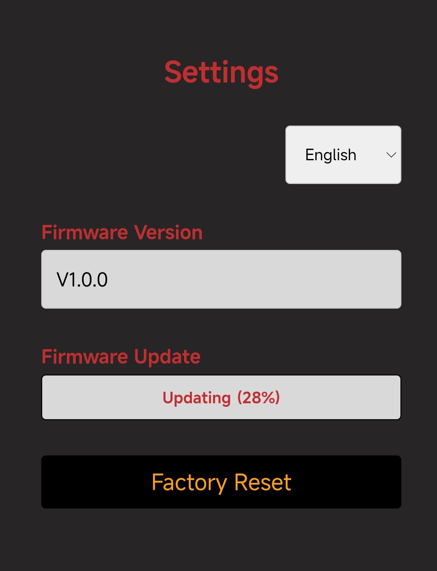
② Choose Language (Default: English)
-
③ Show Current Firmware Version
-
④ Firmware OTA Update: Select a
.binfile for the update.- Click
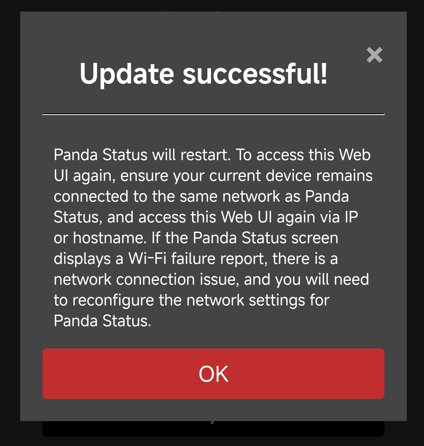
Select .bin Fileto choose the .bin file for the OTA update.

- Wait for the progress to complete, and the device will automatically restart once the update is finished.
- Click
-
⑤ Click to Confirm Restore Factory Settings
Control Page
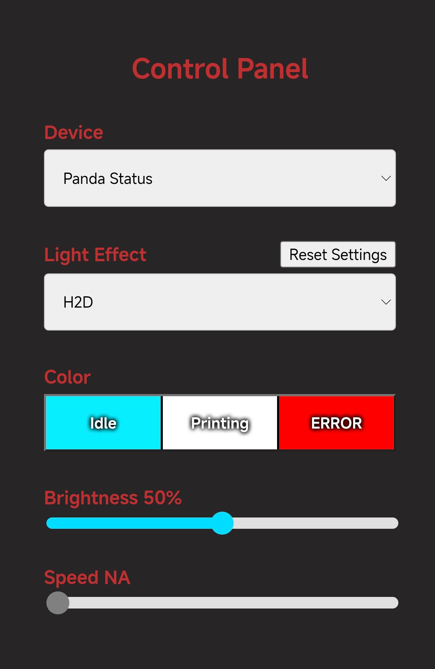
- Elements and Functions
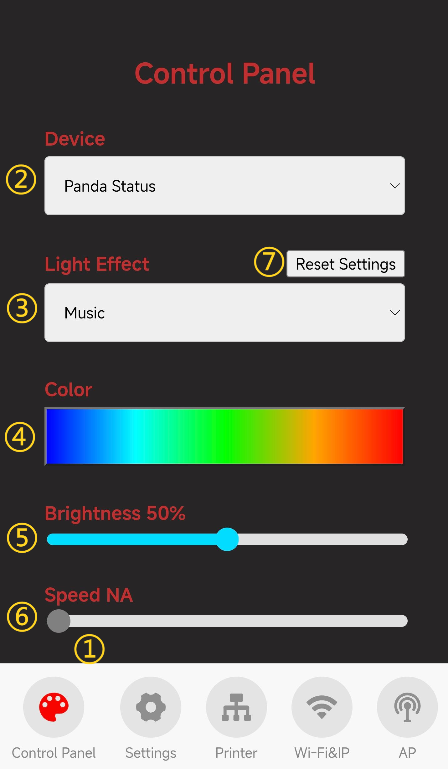
- ① Control Page Selection: When you click the icon, it will turn red to indicate that you are on the Control page.
- ② Current Device Name
- ③ Current Device Mode
- ④ Current Mode's Light Effects
- ⑤ Brightness
- ⑥ Speed
-
⑦ Clicking the
Reset Settingsbutton will restore the brightness for both Music and H2D modes to the factory default (50%). Additionally, the colors for the three printing states will be reset to their default settings. -
Device Modes
-
Mode 1: Music (Factory Default Mode)

Brightness is set to 50% by default, adjustable from 0 to 100%.
In this mode, RGB lights pulse rhythmically with the audio level, changing color from Blue → Green → Yellow → Orange → Red. Specific light effects:
-------- Low Audio -------- ---- Medium Audio ---- ---------High Audio -------- 
-
Mode 2: H2D Style

Brightness is set to 50% by default, adjustable from 0 to 100%.
In this mode, the RGB light will display various effects based on the printer's current status, as follows:
Idle State: White breathing light (customizable color settings for this state: How to set the color)
Downloading Files: Yellow flow.
Pre-print Preparation: Yellow-orange flowing light.
Printing: White solid light that fills proportionally based on the printing percentage (customizable color settings for this state: How to set the color)

Print Completed: Green light stays on for 30 seconds before switching to the idle state light effect (default is white breathing light).

Print Paused: White breathing light.
Print Error: Red flashing light (customizable color settings for this state: How to set the color)
Customizing Light Color
-
To set the color (using the idle state as an example):
-
In the control page, select the H2D mode. Under the "Color" option, you will see three boxes: Idle-white breathing light, Printing-white solid light that fills based on progress, and Error-red flashing light.
-
Select the idle state and click
Confirmbutton.
-
You will then be directed to the color selection page.
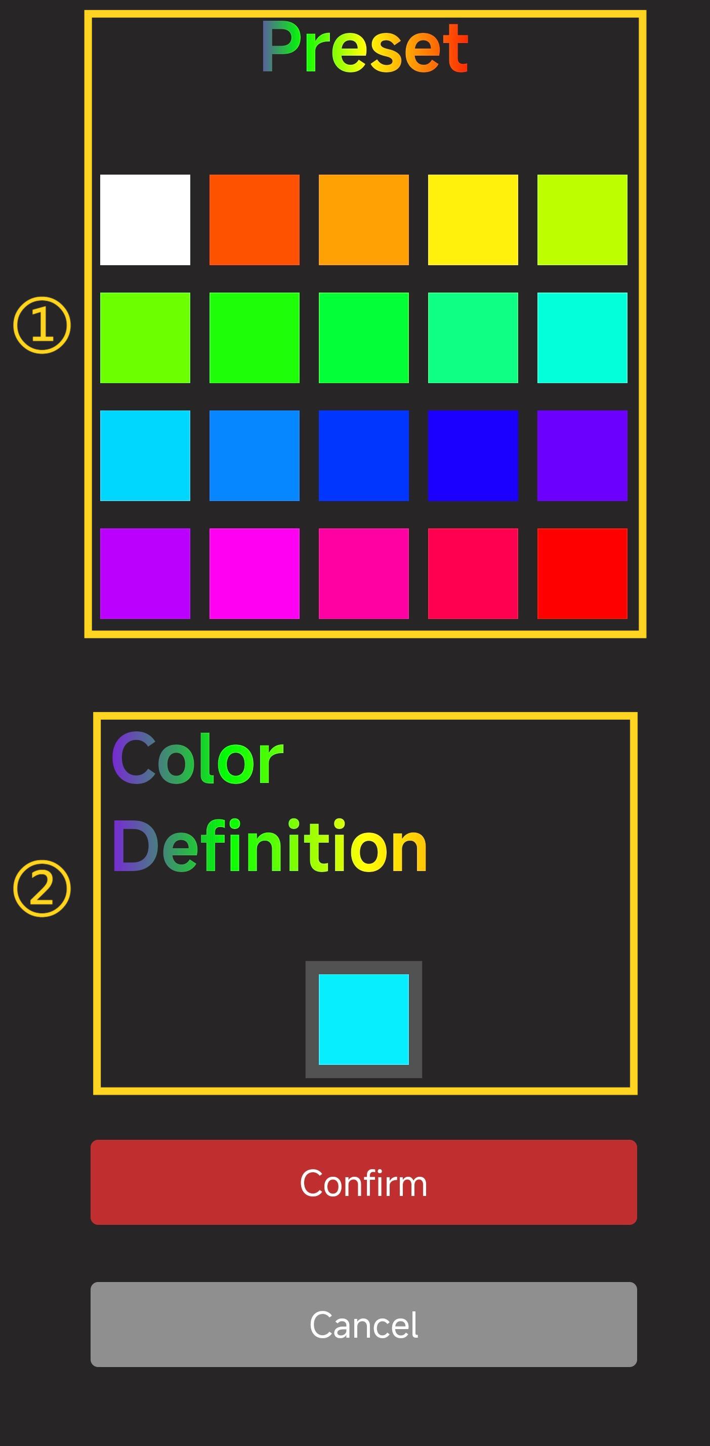
- ① Factory default preset color.
- ② Custom color
-
After selecting a color block, click
Confirm.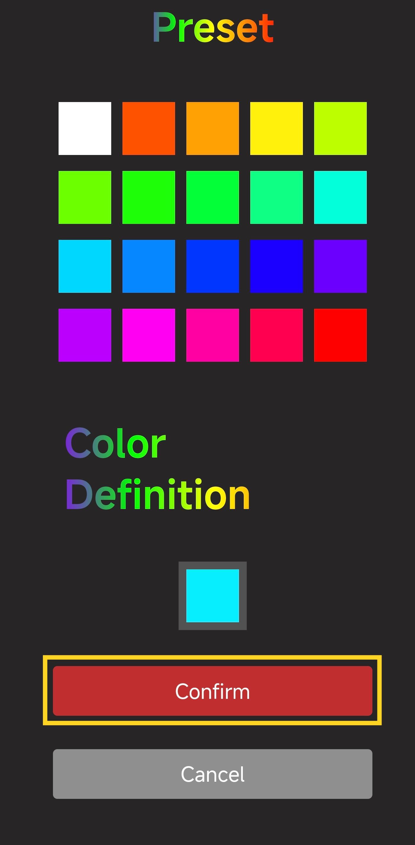
-
The white idle light will change to the selected color, such as sky blue.
Firmware History
V1.0.0
- First released factory firmware.
V1.0.1
-
Change the access address of the AP web page from "192.168.4.1" in the factory firmware to "192.168.254.1" to avoid IP conflicts for users (users need to restore the factory Settings for this condition to take effect).
-
Modify the firmware version from "V1.0.0" to "V1.0.1"
-
After printing is completed, the green light remains on for 15 minutes and then changes to the idle mode light effect
-
In non-MUSIC mode, if no print is made in the idle state for more than 120 minutes, it will automatically switch to standby mode and light up when the next print is initiated. When a user accesses or operates the Web UI or prints, the light bar is awakened (the light bar lights up).
Feature Requests
If you'd like to see certain features in the upcoming firmware release, please submit a feature request on the official GitHub repository. Feature Requests