SKRat

Product Profile
BIGTREETECH SKRat v1.0 is a 3D printer motherboard jointly launched by Shenzhen BIQU Innovation Technology Co., Ltd. and Rat Rig.
Product Link: https://biqu.equipment/products/bigtreeetech-skrat-v1-0-control-board
Features Highlights
- 32-bit 64 MHz ARM Cortex-M0+ series STM32G0B1VET6 MCU.
- Onboard BOOT button to enable DFU mode to update the bootloader.
- The thermistor circuit is protected to prevent MCU damage from shorted heated bed and heater cartridge connection.
- Four 2-pin fan ports, one always-on fan port, and two 4-pin fan ports.
- All fans can realize VIN, 12V, 5V voltage selection via jumpers, and different voltages can be set separately for different ports.
- Integrated SPI and UART mode of TMC driver and DIAG pin, easily configurable with jumpers.
- Supports power loss recovery, filament runout sensor, auto power-off, BLTouch, proximity switch, RGB, etc.
- Onboard non-spring loaded microSD card slot for upgrading and configuring firmware through microSD card, which is simple, convenient, and efficient.
- Onboard CAN bus port.
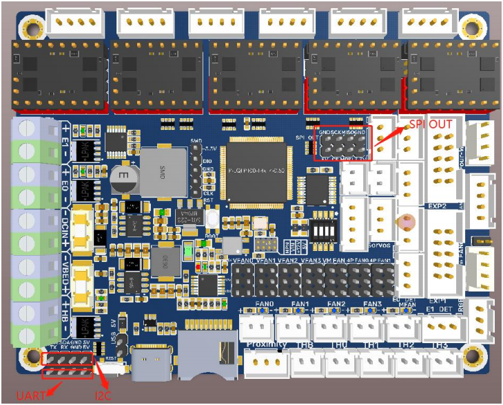
- The SPI expansion port is +3.3V and +5V selectable, which is convenient to connect expansion modules, such as an ADXL345 accelerometer.
- Onboard UART and I2C expansion output ports.
Specifications
| Dimensions | 110 x 85mm, for details please refer to BTT SKRat_V1.0_SIZE |
|---|---|
| Mounting Size | 110 x 85mm |
| MCU | ARM Cortex-M0+ STM32G0B1VET6 |
| Input Voltage | DC12V-DC24V |
| Logic Voltage | DC 3.3V |
| Heater Connection | Heated Bed (HB), Heater Cartridge (HE0, HE1) |
| HB Port Max. Current | 10A Continuous, 15A Instantaneous |
| Heater Cartridge Max. Current | 8A Continuous, 10A Instantaneous |
| Fan Port | 4 x CNC, 1 x Always On, 2 x 4-pin Header |
| Fan Port Max. Current | 1A Continuous, 1.5A Instantaneous |
| Overall Current (Heater Cartridge +Drivers+All Fans) | <15A |
| Expansion Port | BLTouch (Servos, Probe), PS-ON, PWR-DET, Fil-DET, RGB, CAN-FD, SPI, UART, I2C |
| Stepper Driver Mode | SPI, UART, STEP/DIR |
| Stepper Motor Socket | X, Y, Z (Dual Z axes), E0, E1 5 channels in total |
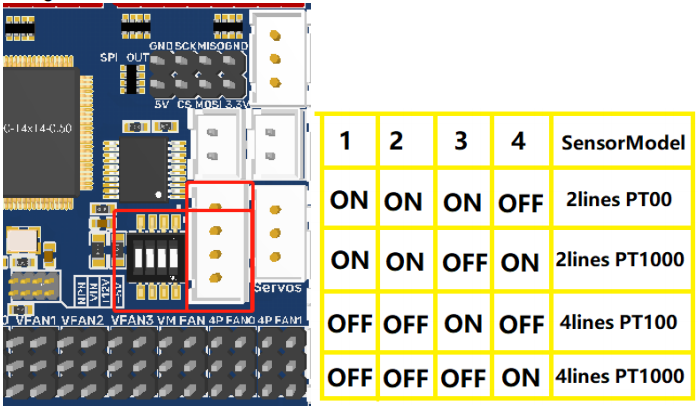
| Thermistor | 5 x NTC Ports, 1 x PT100/PT1000 |
| Display | 2.4-inch TFT, 3.5-inch TFT, LCD12864 Screen... |
| PC Connection | Type-C |
| Supported File Format | G-code |
| Recommended Slicer/Console | Cura, Simplify3D, Pronterface, Repetier-host, Makerware |
Firmware
Supported Firmware: Marlin, Klipper
Dimensions
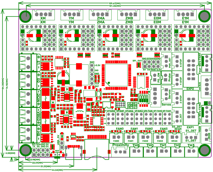
Peripheral Interface
Interface Diagram
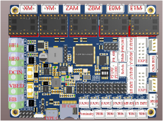
Pin Description
|
|
Info
For details please refer to BIGTREETECH SKRat V1.0-Pin.pdf.
Interface Introduction
LED Indicator Light
After the motherboard is powered on:
Power-Red Light-Power Indicator: The solid red light indicates normal motherboard power.
Status-Green Light-Status Indicator: When updating firmware, this light will flash and then be controlled by the firmware.
D10-Green Light-HB (Heated Bed) Status Indicator: The light will remain solid green when the heated bed is working and turn off when it is not.
D3, D6-Green Light-E0, E1 (Heater Cartridge) Status Indicator: The light will remain solid green when the heater cartridge is working and turn off when it is not.
FAN0, FAN1, FAN2, FAN3-Blue Light-CNC Fan Status Indicators: The blue lights turn on when the corresponding CNC fan is running and turn off when the fan is off.
MFAN-Blue Light-MFAN Status Indicator: The blue light will remain on when the power supply is normal.
USB Power Supply
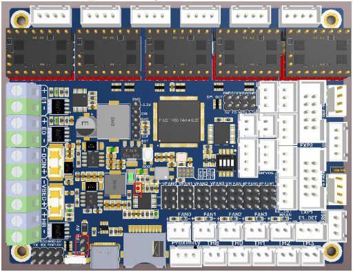
After the SKRat has been powered, the Power-Red Light on the middle of the board will light up, indicating power on. If using USB to power the board, please short the USB_5V with a jumper.
Downloading Firmware via DFU
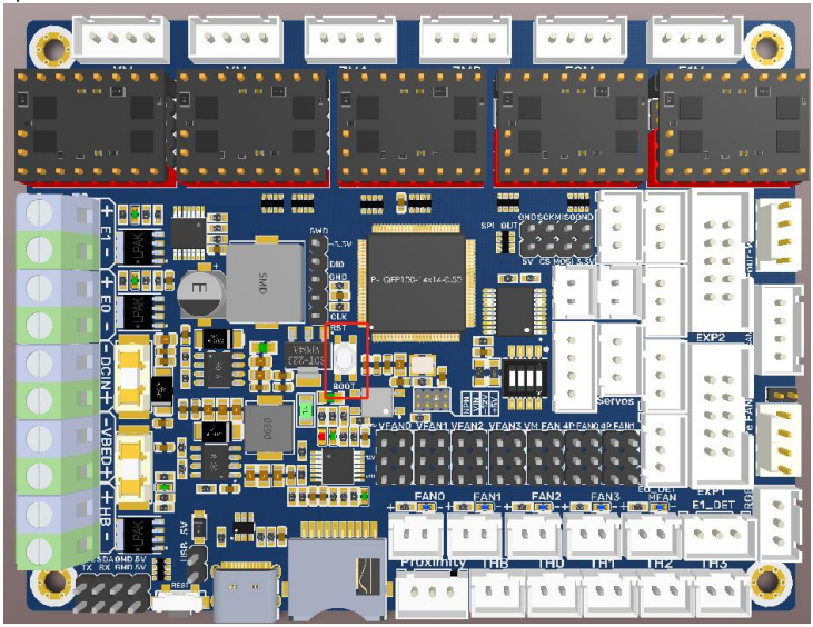
Press and hold the BOOT button, power on the motherboard, and the chip will enter the DFU mode. At this time, you can connect the board to the PC via the Type-C port, and update the firmware via DFU mode.
Stepper Motor Drivers
To Choose the Working Mode of the TMC Driver STEP/DIR
e.g.: A4988, DRV8825, LV8729, ST820, etc., connect jumpers(MS0-MS2) according to the microstep table below.

For details, please click: https://bigtreetech.github.io/docs/Tutorials.html
UART mode of TMC driver
e.g.: TMC2208, TMC2209, TMC2225, etc., place jumpers according to the diagram below, microstep and current can be configured in firmware.

SPI mode of TMC driver
e.g.: TMC2130, TMC5160, TMC5161, etc., place jumpers according to the diagram below, microstep and current can be configured in firmware.

Sensorless Homing
When using sensorless homing, place jumpers according to the diagram below.

Note: The extra ENDSTOP cannot be used by selecting this function! ! !
Fan Voltage Selection
+5V
Use a jumper cap to short the horizontal pins highlighted in the figure below.

12V
Use a jumper cap to short the horizontal pins highlighted in the figure below.

VIN
Use a jumper cap to short the horizontal pins highlighted in the figure below.

Note: Shorting the pins, as shown in the figure below, is strictly prohibited as it may result in permanent damage to the motherboard.

2-pin Fan Wiring
Onboard four 2-pin fan ports (FAN0,FAN1,FAN2,FAN3), one always on fan port(MFAN).

4-pin Fan Port Wiring
Onboard two 4-pin fan ports: Four-Wire FAN0, Four-Wire FAN1.

Note: Using a voltage that does not match a fan's rated working voltage can cause abnormal fan operation or damage. Always ensure that the selected voltage matches the fan's rated working voltage.
Proximity Switch
Voltage Selection
Use a jumper cap to short the corresponding pin to choose +12V, +5V, VIN, as shown in the figure below.

PNP/NPN Type
PNP Type: no need for a jumper cap.
NPN Type: place a jumper cap.

Note: Shorting the pins, as shown in the figure below, is strictly prohibited as it may result in permanent damage to the motherboard.
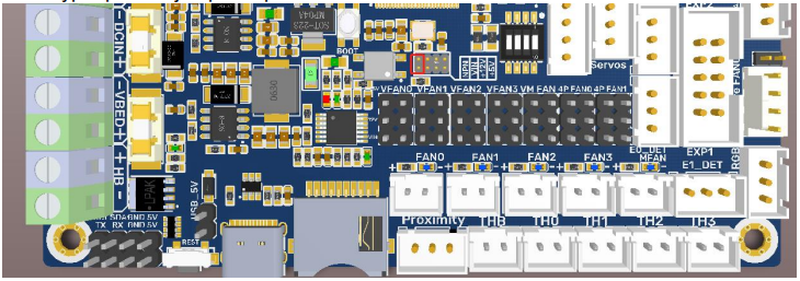
Proximity Switch Wiring

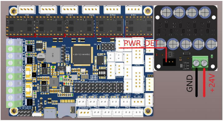
Auto Power off (BIGTREETECH Relay V1.2) Wiring

Power Loss Recovery (BTT UPS 24V V1.0) Wiring
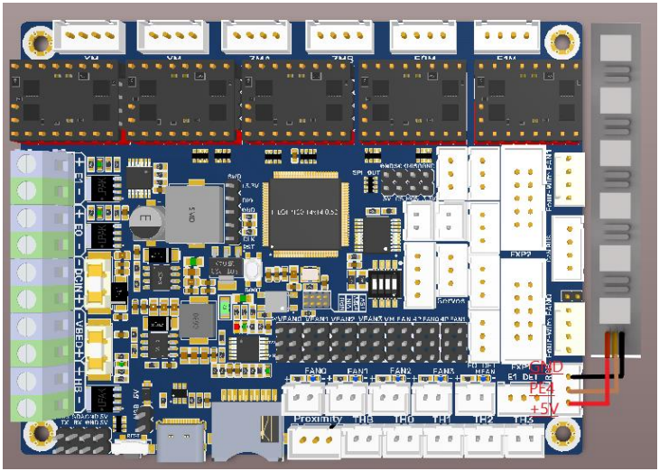
RGB Wiring
BLTouch Wiring

Filament Sensor Wiring
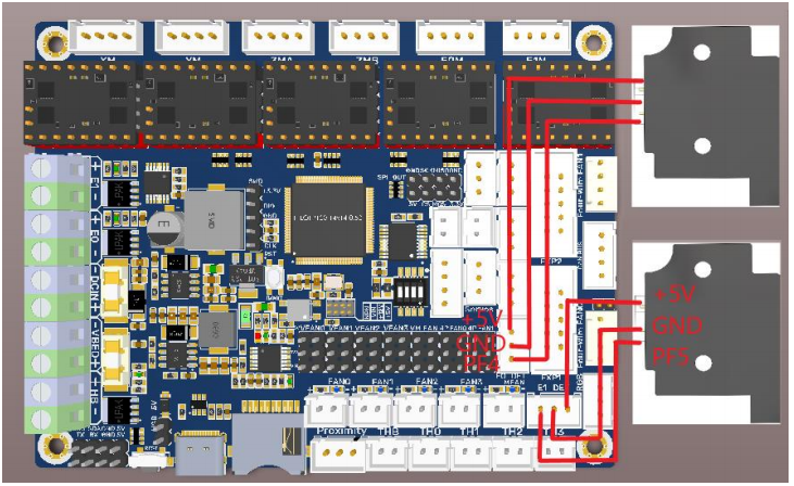
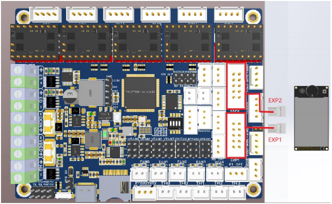
LCD Display Wiring
SPI, I2C, UART
100K NTC
When using a 100K NTC thermistor, the NTC resistor is connected to THB, TH0-TH3, and the pull-up resistance of TH0-TH3 is 4.7K 0.1%.

Using PT100/PT1000 via MAX31865:
CAN bus Wiring
Connect the CAN bus sensor to the CAN bus port on the board.
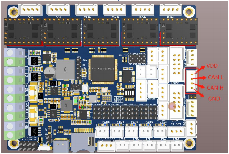
Note: The output voltage of the motherboard CAN bus port is the same as its input voltage.
Marlin
For details, please click:https://bttwiki.com/SKR%203.html#marlin
Klipper
For details, please click:https://bttwiki.com/SKR%203.html#klipper
Firmware Update
For details, please click:https://bttwiki.com/SKR%203.html#firmware-update
Precausions
For details, please click:https://bttwiki.com/SKR%203.html#precausions
FAQ
For details, please click:https://bttwiki.com/SKR%203.html#faq